
Plasma-generating plug

A spark plug and plasma technology, which is applied in the field of ion generating spark plugs, can solve problems such as interfering with the good operation of spark plugs, and achieve the effect of avoiding temperature uniformity.

Active Publication Date: 2009-02-11
RENAULT SA
View PDF0 Cites 15 Cited by
  • Summary
  • Abstract
  • Description
  • Claims
  • Application Information

AI Technical Summary

Problems solved by technology

Carbon deposits will interfere with the good functioning of the spark plugs by creating leakage lines

Method used


Image

  • Plasma-generating plug
  • Plasma-generating plug
  • Plasma-generating plug

Examples


Embodiment Construction

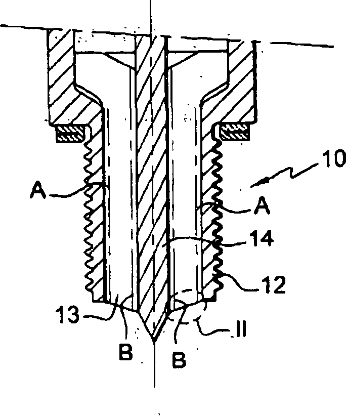
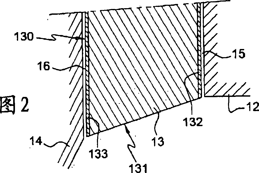
[0017] [17] A radio frequency plasma generating spark plug 10 according to the present invention is shown in figure 1 with Figure 2 on. Like the spark plugs according to the prior art, the RF plasma spark plug comprises a tubular housing 12 housing a dielectric insulator 13 . The housing 12 forms an electrode which is normally grounded. The insulator 13 includes a central cavity 130 in which a central electrode 14 is disposed.

[0018] [18] The insulator is made of ceramic, for example silicon nitride, but the insulator can also be made of glass ceramic or an amorphous material such as quartz.

[0019] [19] According to the present invention, the insulator 13 includes a metal-coated surface. These areas are in figure 1 Indicated by a dotted line. The first area A extends over a cylindrical portion of the insulator facing the housing 12 . The second region B extends over the cavity 130 of the insulator 13 facing the central electrode 14 . The frusto-conical surface 131 o...


PUM


Abstract

The invention relates to a plasma-generating spark plug which undergoes excitation in the radio frequency domain. The invention comprises at least one first metallic electrode (12, 14), an insulator (13), one of which is equipped with a housing (130) in which the other element (13, 14) is mounted with a gap (15, 16) therebetween. The surface of the insulator (13) opposite the first electrode (12,14) is metallised.

Description

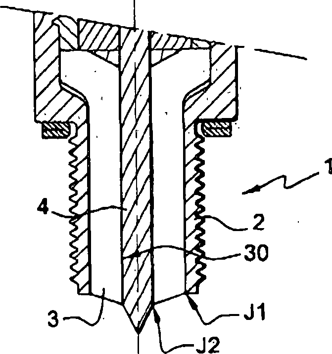
technical field [0001] [01] The present invention relates to a plasma-generated spark plug of the type described for use in a steerable ignition engine. Background technique [0002] [02] Plasma-generating spark plugs are known to be excited in the radio frequency domain (ie greater than 1 MHz), allowing a wider spark than conventional spark plugs to be obtained. One such spark plug (hereinafter referred to as "RF plasma generating spark plug") utilizes a small potential difference to generate a spark of a larger size. The spark plug 1 has been shown in FIG. 3 , comprising a tubular housing 2 containing a dielectric insulator 3 . The housing 2 forms a generally grounded (mass) electrode. The insulator 3 comprises a central cavity 30 in which a central electrode 4 is located. The insulator 3 separates the electrodes 2, 4 in the region where the distance between said electrodes is the smallest; thus, the spark formed between said electrodes is guided on the surface of the i...

Claims


Application Information

Patent Timeline
Patent Type & Authority Applications(China)
IPC IPC(8): H01T13/52H01T13/34H01T13/36H01T13/50
CPCH01T13/52H01T13/36H01T13/50H01T13/34H01T13/00
Inventor X·雅弗勒齐克A·阿涅雷
Owner RENAULT SA
Learn More