
C type folded milling-drilling-riveting combined processing center and method of use thereof

A combined processing, milling and drilling technology, applied in metal processing, metal processing equipment, metal processing machinery parts, etc., can solve the problems of backward technical level, high labor intensity, low work efficiency, etc., and achieve good automatic milling and hole processing. , The effect of high work efficiency and large processing range

Inactive Publication Date: 2009-02-11
ZHEJIANG UNIV +1
View PDF1 Cites 27 Cited by
  • Summary
  • Abstract
  • Description
  • Claims
  • Application Information

AI Technical Summary

Problems solved by technology

After the drilling is completed from the outside, the rivet is inserted, and the operator on the inside positions and operates the inside drilling and riveting tool according to the riveting position, and completes the drilling and riveting operation one rivet after another. The work efficiency is low, the labor intensity is high, and the technical level is very backward.

Method used


Image

  • C type folded milling-drilling-riveting combined processing center and method of use thereof
  • C type folded milling-drilling-riveting combined processing center and method of use thereof
  • C type folded milling-drilling-riveting combined processing center and method of use thereof

Examples


Embodiment Construction

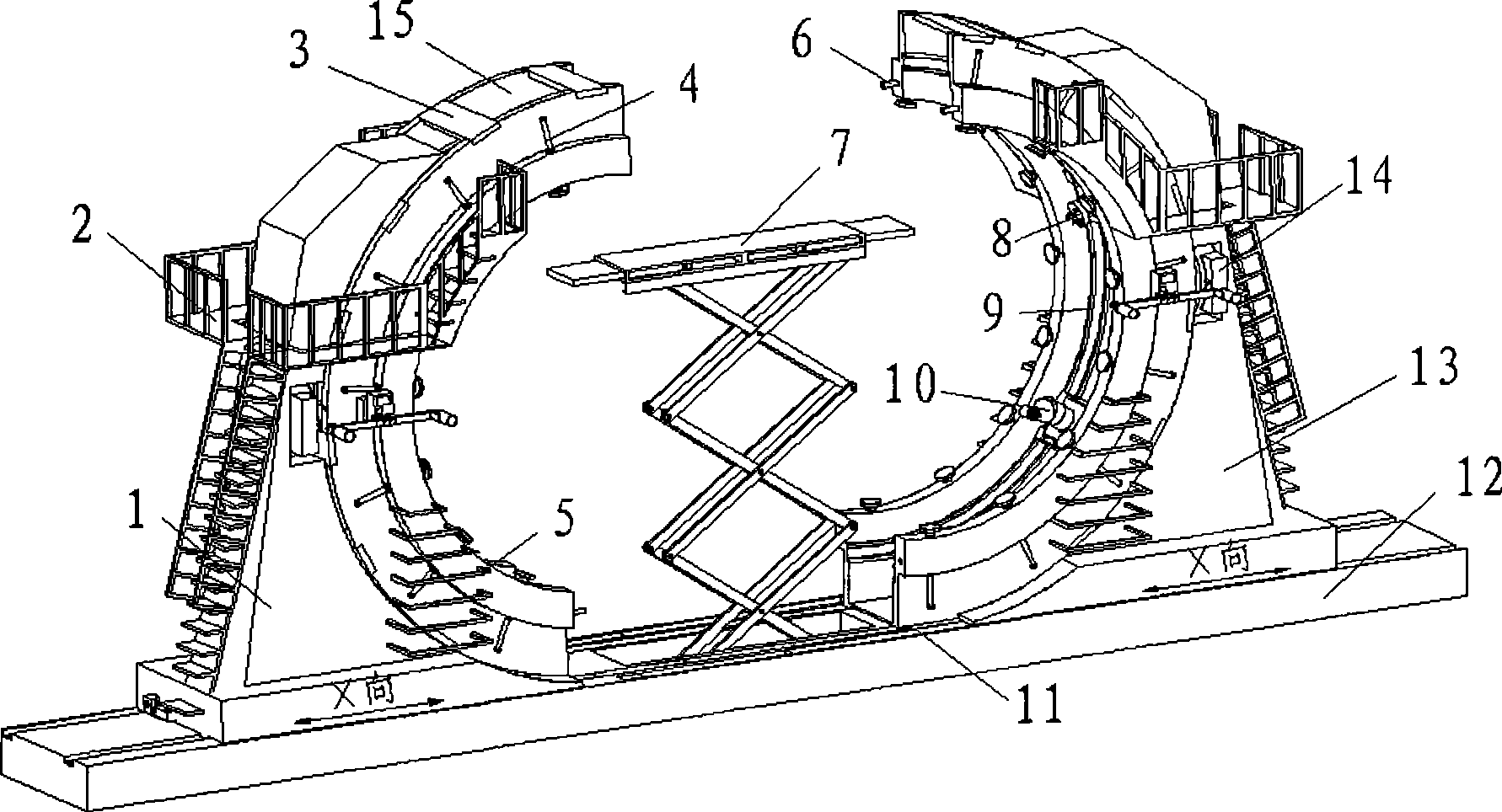
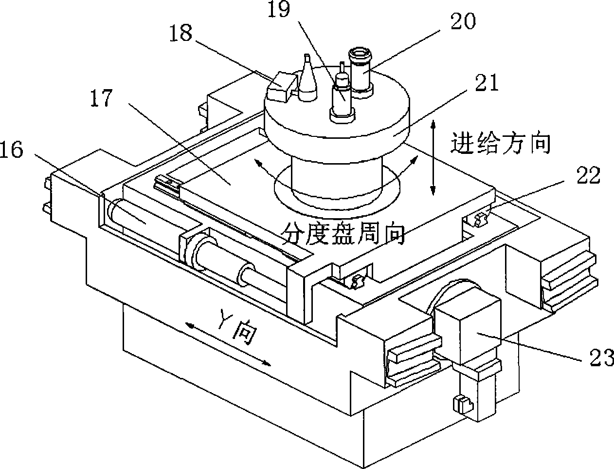
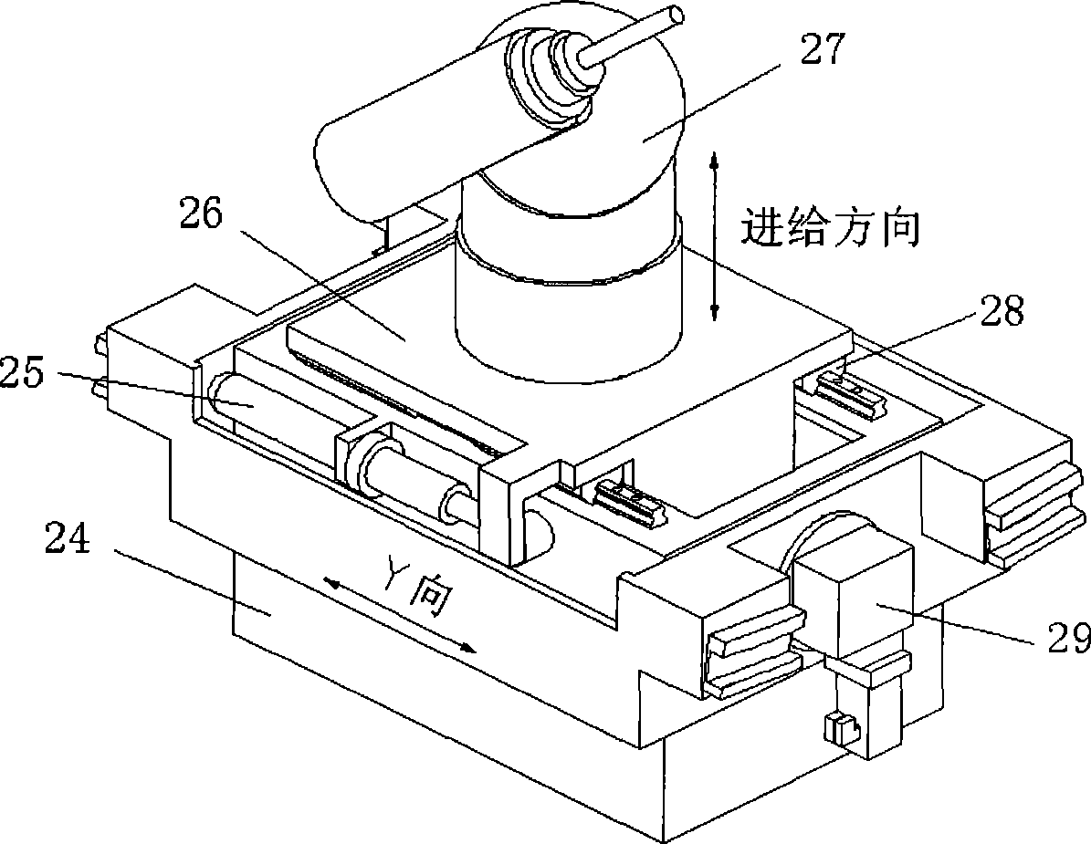
[0030] Such as figure 1 As shown, the C-type combined milling-drilling-riveting machining center includes the left bed of the C-type machine tool 1, the manual operation table 2, the bed connecting rib 3, the pressing device 4, the manual operation ladder 5, and the guide locking device 6. Lifting operation table 7, drilling and riveting device 8, circular guide rail 9, electric spindle power head drilling and milling device 10, guide rail baffle 11, fixed base 12, right bed of C-type machine tool 13, tool changing device 14, semicircle The arc support plate 15, the fixed base 12 are provided with the left bed 1 of the C-type machine tool, the guide rail baffle plate 11, the right bed 13 of the C-type machine tool, and the center of the fixed base 12 is provided with a lifting operation table 7, and the left bed of the C-type machine tool Body 1 and the right bed 13 of the C-type machine tool are respectively provided with two semi-arc support plates 15, and are fixed by the ...


PUM


Abstract

The invention discloses a working principle of a C type involutive milling, drilling and riveting combined machining center and a structure thereof. The body section of a plane can be machined by milling and drilling, and also the structure is provided with counter boring and rivet holding functions. A left machine tool body and a right machine tool body of a C type machine tool are arranged on a fixing base, two semi-circle supporting plates are arranged on the machine tool, a clamping device and a circular guide rail are uniformly distributed on the supporting plate, and a drilling and riveting device and an electric main shaft power head drilling and milling device are arranged on the circular guide rail. The working principle adopt the following machining steps: firstly, the left machine tool body and the right machine tool body are moved on the guide rail, and two semi-circumferential frames are opened; secondly, after the work piece is in position, the two semi-circumferential frames are closed, and the fixing for the work piece is realized; thirdly, after the electric main shaft power head drilling and milling device is in position, the drilling and milling for the work is finished; and fourthly, the working process of the drilling and riveting is similar to the drilling and milling device. The invention has the advantages that firstly, the automatic machining of milling, drilling and riveting of the body section of the plane can be satisfied; secondly, the work piece is ensured to have good passing ability after the machining; and thirdly, the range of circumferential machining and rivet connection range is large, and the working efficiency is high.

Description

technical field [0001] The invention relates to a C-type combined milling, drilling and riveting machining center and its use method Background technique [0002] When assembling large aircraft fuselage sections, it is necessary to process the butt end faces and holes, and then complete the riveting work. The workload of drilling and riveting is huge, and the degree of automation of drilling and riveting directly affects the efficiency and quality of assembly. [0003] In foreign aircraft assembly, large-scale special-purpose machine tools are often used to realize automatic drilling and riveting when the large parts of the aircraft are docked. An automatic riveting machine tool with a large frame structure. Industrial robots are used inside the fuselage to assist riveting in aircraft assembly. This kind of special-purpose machine tool has a large processing range, and can perform automatic riveting in difficult-to-reach areas of aircraft components, and is equipped with a...

Claims


Application Information

Patent Timeline
Patent Type & Authority Applications(China)
IPC IPC(8): B23Q39/00B23Q1/01B23Q1/25B23Q3/06B21J15/10
CPCB21J15/142
Inventor 柯映林贾叔仕蒋君侠李江雄方强王青黄浦缙刘刚郭志敏黄鹏
Owner ZHEJIANG UNIV
Learn More