Polymer film splicing method and device, and stretching method

A technology of polymer film and bonding method, which is applied in the fields of polymer film bonding and devices and stretching, can solve the problems of inability to obtain bonding strength, wrinkles, etc., and achieve the effects of shortening heat transfer distance, preventing pits, and reducing energy saving

Inactive Publication Date: 2009-02-04
FUJIFILM CORP
View PDF6 Cites 7 Cited by
  • Summary
  • Abstract
  • Description
  • Claims
  • Application Information

AI Technical Summary

Problems solved by technology

[0010] Therefore, there is a problem that in the case of joining by welding, sufficient joint strength cannot be obtained, and furthermore, wrinkles are generated on the film subjected to welding, joining, stretching and stress relaxation heat treatment

Method used


Image

  • Polymer film splicing method and device, and stretching method
  • Polymer film splicing method and device, and stretching method
  • Polymer film splicing method and device, and stretching method

Examples


Embodiment approach 1

[0034] As shown in FIG. 1 , an off-line stretching device 2 is used to stretch a TAC film 3 (hereinafter referred to as film 3 ), and includes a film supply chamber 4 , a tenter, and Machine part 5, relaxation chamber 6, cooling chamber 7 and winding chamber 8. The film web 9 prepared in the solution casting apparatus is loaded into the film supply chamber 4 . The film roll 9 is obtained by winding the film 3 in roll form around a core. The film 3 is supplied into the tenter section 5 from the film web 9 loaded in the film supply chamber 4 . In the tenter section 5, the film 3 is continuously stretched in the film width direction while being heated. The stretched film 3 is cooled by the relaxation chamber 6 and the cooling chamber 7 . The cooled film 3 is wound up in the winding chamber 8 . In the tenter section 5, the film 3 is stretched by 100.5% to 300% in the film width direction. In each of the film supply chamber 4, the tenter section 5, the relaxation chamber 6, th...

Embodiment approach 2

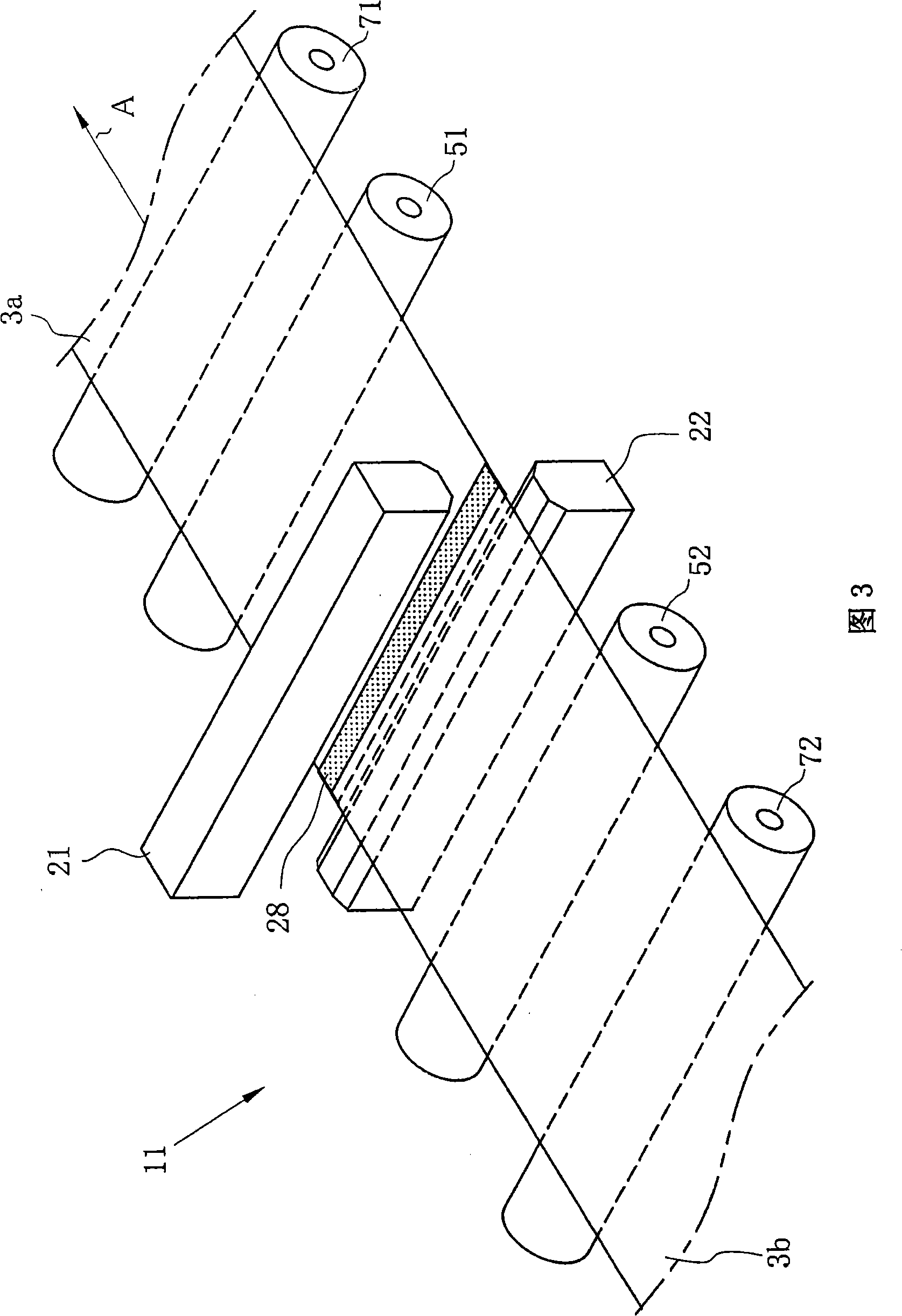
[0060] Although in Embodiment 1, the front film 3a and the rear film 3b are joined to each other using the fusion machine 20 in the joining section 11, alternatively, as in Figure 8 As shown in , an ultrasonic bonder 50 may be used to bond the front film 3a and the rear film 3b.

[0061] The ultrasonic bonder 50 mechanically vibrates the film 3 , for example, 20,000 to 28,000 times / second with an amplitude of 0.03 mm, to heat and fuse the film 3 . The ultrasonic adapter 50 includes two transducers 57 , a horn 59 and a transmitter 53 . Permanent magnets 54 are disposed between transducers 57 . A coil 55 is connected across each transducer 57 . Transmitter 53 causes coil 55 to drive transducer 57 . The transducer 57 converts electrical vibrations into mechanical vibrations. The horn 59 amplifies the mechanical vibration generated by the transducer 57 to apply energy to the rear end of the front membrane 3a and the front end of the rear membrane 3b mounted on the mounting ba...

Embodiment approach 3

[0063] Although in Embodiment 1, the front film 3a and the rear film 3b are joined to each other using the fusion machine 20 in the joining section 11, alternatively, as shown in FIG. Acetone, one of the film solvents, is used for bonding.

[0064] Acetone was applied by spraying to the bonding area 28 at the rear end of the preceding film 3a, and then the leading end of the following film 3b was placed on the rear end of the preceding film 3a. After that, the rear end of the front film 3a and the front end of the rear film 3b were bonded to each other by acetone in a press-contact manner.


PUM


Abstract

The invention relates to a polymer film joint method and a device and a polymer film stretching method. An off-line stretching device includes a film supply chamber, a tenter section, a relaxation chamber, a cooling chamber, and a winding chamber. The film supply chamber includes a splicing section, where a rear end of a preceding film and a front end of a trailing film are overlapped to be spliced to each other by thermal welding. The thermal welding is performed from above and below the film while a temperature of welding heads of a heat sealer, contacting with the film, is kept at a level equal to or less than a decomposition temperature of the preceding and trailing films. The spliced film is stretched in the tenter section and subjected to heat treatment for stress relaxation in the relaxation chamber, to shrink in a film width direction. Since the shrinkage amount of a spliced area and that of a peripheral area become equal to each other, the occurrence of wrinkles in the spliced area and tears of the film in the peripheral area can be prevented. Additionally, since a heat transfer distance between a film surface and a film splicing surface can be shortened, the heating from above and below the film enables high-speed welding.

Description

technical field [0001] The present invention relates to a polymer film joining method and apparatus and a polymer film stretching method. Background technique [0002] Recently, according to the rapid development and popularization of liquid crystal displays (LCDs) and the like, the demand for cellulose ester (cellulose acylate) films, especially triacetyl cellulose (TAC) films used as protective films and the like for LCDs, is increasing. In accordance with the increase in demand for TAC films, there is a need to increase their productivity. TAC membranes were prepared as follows. The dope including TAC and solvent is casted onto a continuously moving support through a casting die to form a cast film thereon. The cast film is dried or cooled to solidify. The solidified cast film is peeled off from the support to form a wet film. The wet film was dried and rolled into a film. According to the solution casting method described above, a film containing fewer impurities an...

Claims


Application Information

Patent Timeline
IPC IPC(8): B29C65/20B29C55/08B29C71/02B29L7/00
CPCB29C66/1122B29C65/08B29C65/18B29C65/305B29C65/4895B29C65/5057B29C66/0342B29C66/344B29C66/43B29C66/71B29C66/81417B29C66/81419B29C66/8322B29C66/83221B29C66/91231B29C66/91421B29C66/9161B29C66/919B29C66/9513B29C66/9517B29C66/961B29K2001/12B29K2001/08
Inventor 青岛伸介
Owner FUJIFILM CORP
Why Eureka
Try Eureka