
Method for controlling a vehicle equipped with a mechanical servo transmission

A control method and servo controller technology, applied in the direction of transmission control, mechanical equipment, components with teeth, etc., can solve the problem of lengthy and heavy initial calibration of mechanical servo transmission devices

Active Publication Date: 2009-01-28
FAB ITAL MAGNETI MARELLI SPA
View PDF2 Cites 9 Cited by
  • Summary
  • Abstract
  • Description
  • Claims
  • Application Information

AI Technical Summary

Problems solved by technology

Thus, the initial calibration of a vehicle's mechanical servo drive is a lengthy, tedious, and skilled technician's intervention

Method used


Image

  • Method for controlling a vehicle equipped with a mechanical servo transmission
  • Method for controlling a vehicle equipped with a mechanical servo transmission

Examples


Embodiment Construction

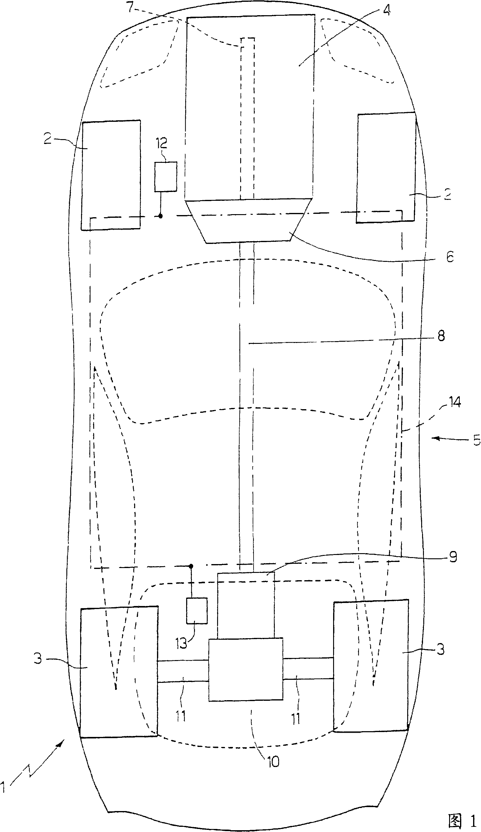
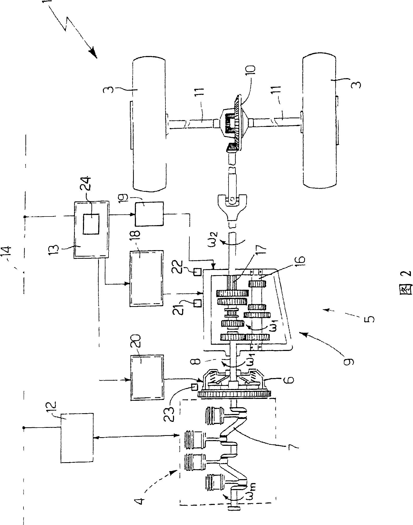
[0024] In FIG. 1 , reference numeral 1 denotes the whole of a motor vehicle provided with two front wheels 2 and two rear drive wheels 3 which receive the torque generated by the internal combustion engine 4 through a servo transmission 5 . The servo transmission 5 comprises a servo clutch 6 housed in a bell fixed relative to the engine 4 and designed to connect the transmission shaft 7 of the engine 4 to a transmission shaft 8 which 8 terminates in a servo transmission 9 arranged on the rear axle. A self-locking differential 10 is connected in cascade to said servo transmission 9, from which a pair of drive shafts 11 extend, each of said drive shafts 11 being opposite to a respective rear drive wheel 3 fixed.

[0025] The automobile 1 comprises an engine control unit 12 (schematically shown), a transmission control unit 13 (schematically shown), and a line 14 bus (BUS) implementing a CAN (Automotive Local Network ) agreement and extended to the entire car1. Both the engine...


PUM


Abstract

A method for controlling a vehicle presenting the steps of: verifying, at starting of an internal-combustion engine, whether a memory of calibrations contains the function of transmissibility of a clutch and / or the effective positions of engagement and selection of the gears in a gearchange; sending to the driver, if the memory of calibrations does not contain the function of transmissibility of the clutch and / or the effective positions of engagement and selection of the gears in the gearchange, a signal of start of a first self-calibration step, during which the driver must leave the internal-combustion engine turned on and the vehicle stationary; selecting and engaging a number of times, during the first self-calibration step, all the gears of the gearchange autonomously from the driver for determining the effective positions of engagement and selection of the gears in the gearchange; disengaging and engaging, during the first self-calibration step, the clutch with the gearchange in neutral and autonomously from the driver for determining a point of start of engagement of the clutch; and sending to the driver, at the end of the first self-calibration step, a signal of end of the first self-calibration step.

Description

technical field [0001] The invention relates to a method for controlling a vehicle equipped with a mechanical servo transmission. Background technique [0002] Mechanical servo drives are becoming more and more popular. Mechanical servo transmissions have a similar construction to conventional types of manual transmissions, except that the driver-operated clutch pedal and gear lever are replaced by corresponding electronic or hydraulic servo controls. [0003] When using a mechanical servo transmission, the driver only needs to operate (for example, using two control levers arranged on opposite sides of the steering column) the transmission control unit to change to a higher gear or a lower gear, the transmission The control unit performs automatic gear changes both by acting on the engine and by acting on servo controls connected to clutches and gearchanges. [0004] Typically, a mechanical servo transmission includes three separate hydraulic actuators that drive clutch e...

Claims


Application Information

Patent Timeline
Patent Type & Authority Applications(China)
IPC IPC(8): B60W10/02B60W10/06B60W10/10F16D48/06F16H61/28B60W10/18B60W30/18
CPCF16H2061/0053F16D2500/3026F16D48/06F16H2061/283B60W10/02F16H2342/02B60W10/184F16H2342/042F16D2500/7101F16D2500/7106F16D2500/50263B60W30/18054F16H61/28B60W30/18B60W10/11F16D2500/70264
Inventor 法布里齐奥·阿米萨诺切萨雷·索拉
Owner FAB ITAL MAGNETI MARELLI SPA
Learn More