
Mask for screen printing and screen printing method using the same

A technology of screen printing and masking, which can be used in screen printing, screen printing machines, printed circuits assembled with electrical components, etc., and can solve problems such as low quality

Inactive Publication Date: 2009-01-28
SAMSUNG ELECTRO MECHANICS CO LTD
View PDF1 Cites 15 Cited by
  • Summary
  • Abstract
  • Description
  • Claims
  • Application Information

AI Technical Summary

Problems solved by technology

[0013] In order to arrive at the present invention, intensive and thorough studies aimed at solving the problems encountered in the related art have led to the discovery that a protrusion can be additionally formed in the peripheral area of ​​the screen mask, thus making it possible to solve the problems between the substrate and the screen mask. Problems with poor quality when plates separate between molds

Method used


Image

  • Mask for screen printing and screen printing method using the same
  • Mask for screen printing and screen printing method using the same
  • Mask for screen printing and screen printing method using the same

Examples


Embodiment Construction

[0029] Hereinafter, a detailed description will be given of the present invention with reference to the accompanying drawings.

[0030] In the present invention, there is provided a new screen mask having a structure that provides uniform conditions for board separation regardless of the position of the substrate and is not affected by shearing at the time of board separation. Deformation of the solder paste due to shear stress.

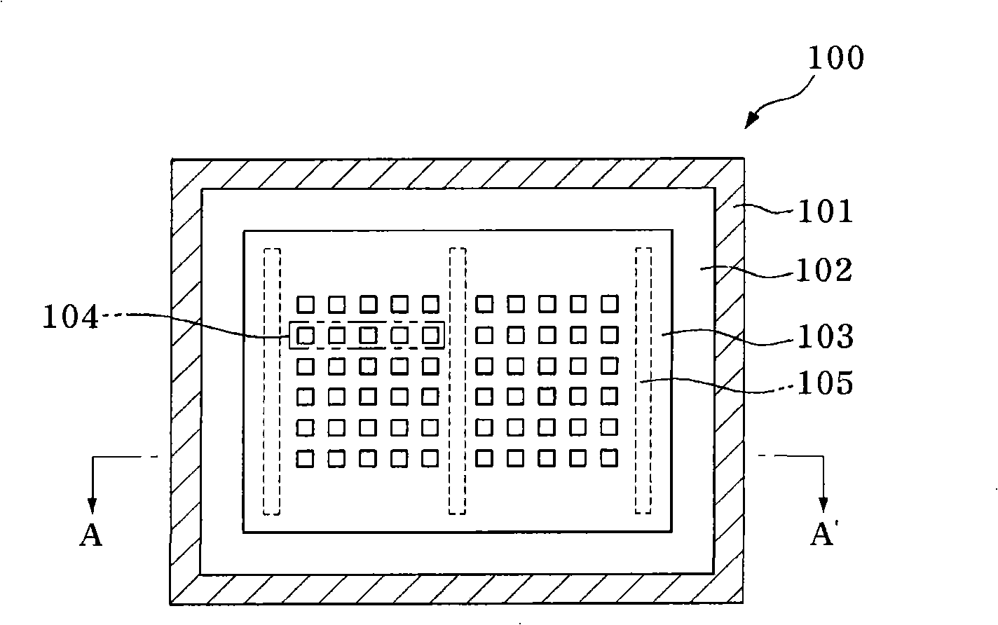
[0031] figure 1 is a top view illustrating a mask for screen printing according to the present invention, and figure 2 is along figure 1 A cross-sectional view taken along the line A-A'.

[0032] refer to figure 1 and figure 2 , the mask 100 for screen printing according to the present invention includes: a mask body composed of a plurality of pattern areas 104 having holes for screen printing and a peripheral area 103 surrounding the outside of the pattern areas; and protrusions 105 , formed in the peripheral region 103 on the backside of...


PUM


Abstract

This invention relates to a mask for screen printing, which includes a mask body composed of a plurality of pattern areas having holes for screen printing and a peripheral area surrounding the outside of the pattern areas; and a protrusion portion formed in the peripheral area of a back surface of the mask body, and to a screen printing method using the same.

Description

[0001] Cross References to Related Applications [0002] This application claims priority to Korean Patent Application No. 10-2007-0075740, filed on July 27, 2007, entitled "Mask for Screen Printing and Screen Printing Method Using the Same", and will The entire contents of which are incorporated by reference in this application. technical field [0003] The present invention generally relates to a mask for screen printing and a screen printing method using the same. More specifically, the present invention relates to a mask for screen printing comprising a mask on the back of its mask body and a screen printing method using the mask. The protrusion (protrusion portion) in the peripheral area (peripheral area), thereby achieving a greatly improved effect of plate separation. Background technique [0004] In the case where a printing agent such as solder paste (solder paste) is printed using a screen mask, it is very important to obtain uniform printing quality. Factors af...

Claims


Application Information

Patent Timeline
Patent Type & Authority Applications(China)
IPC IPC(8): B41F15/36B41M1/12H05K3/34H05K3/12
CPCH05K3/1225B41P2215/12
Inventor 曹淳镇文先载崔晋原
Owner SAMSUNG ELECTRO MECHANICS CO LTD
Learn More