Eureka AIR delivers breakthrough ideas for toughest innovation challenges, trusted by R&D personnel around the world.

Deep layer terrestrial heat renewable energy source winter heating method

A renewable energy, deep-seated technology, applied in the direction of renewable energy integration, geothermal power generation, heating methods, etc., can solve the problems of backward comprehensive energy-saving technology, high one-time cost, complex technology, etc., and achieve high practical value and promotion value , Renewable operating costs, endless effects

Inactive Publication Date: 2009-01-21
赵铭
View PDF0 Cites 46 Cited by
  • Summary
  • Abstract
  • Description
  • Claims
  • Application Information

AI Technical Summary

Problems solved by technology

[0002] In the current field of geothermal energy development and utilization of dry hot rocks in the deep crust, the thermodynamic research on using water to flow in the deep well casing to extract low-grade heat energy (40-80 degrees) from the deep crust for heating is due to high cost, complicated technology, and small scope of application. (It can only be used for heating in winter and cannot be used for power generation) Therefore, thermodynamic research institutions around the world have not studied this in depth
[0003] At present, the room temperature control in general buildings in developed countries mainly relies on heat pump technology to achieve heating and cooling. The energy-saving benefits of 1:4 heat pumps can not only keep the building at a constant temperature (22-24 degrees) throughout the year, but also its economical and Energy consumption is within an acceptable range, so a single heating technology cannot replace the use of heat pump technology in two seasons, so developed countries have not been developed; while developing countries are due to the high one-time cost of this technology and comprehensive energy saving. Problems such as backward technology make it impossible to carry out research work on deep geothermal utilization

Method used


Image

  • Deep layer terrestrial heat renewable energy source winter heating method
  • Deep layer terrestrial heat renewable energy source winter heating method
  • Deep layer terrestrial heat renewable energy source winter heating method

Examples


Embodiment Construction

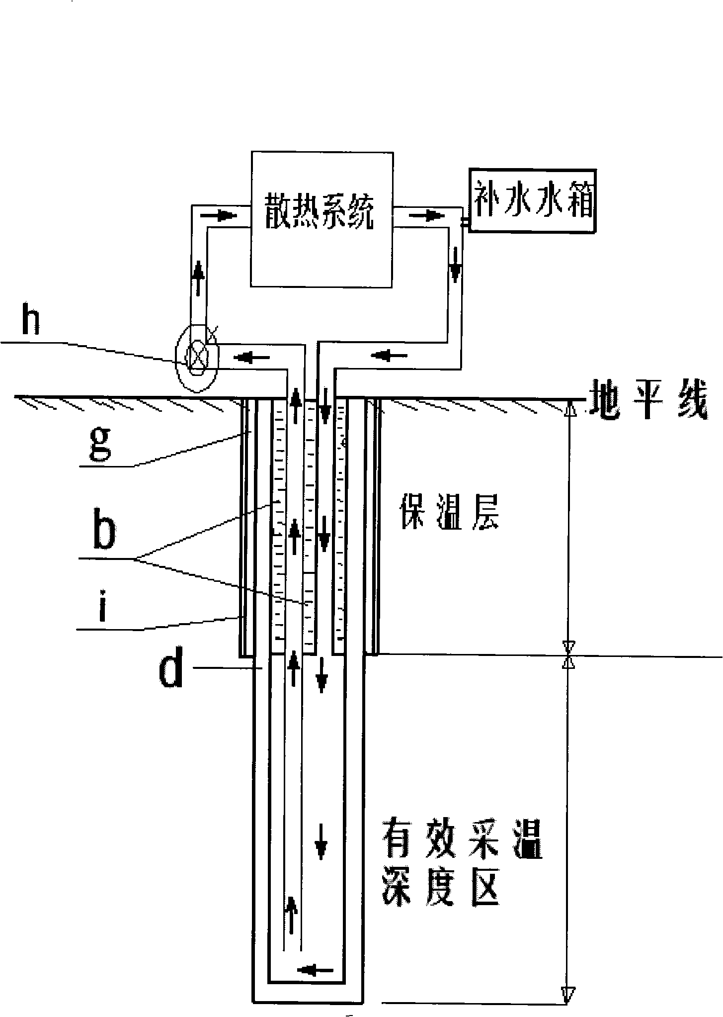
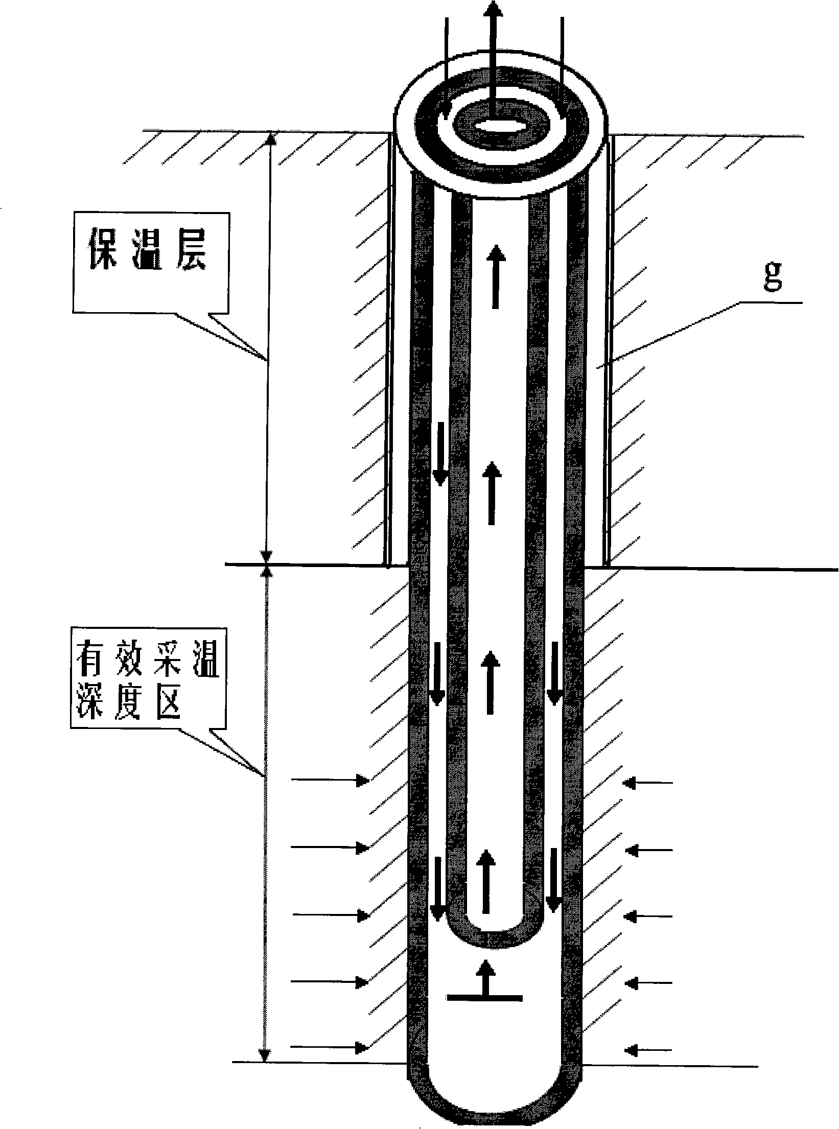
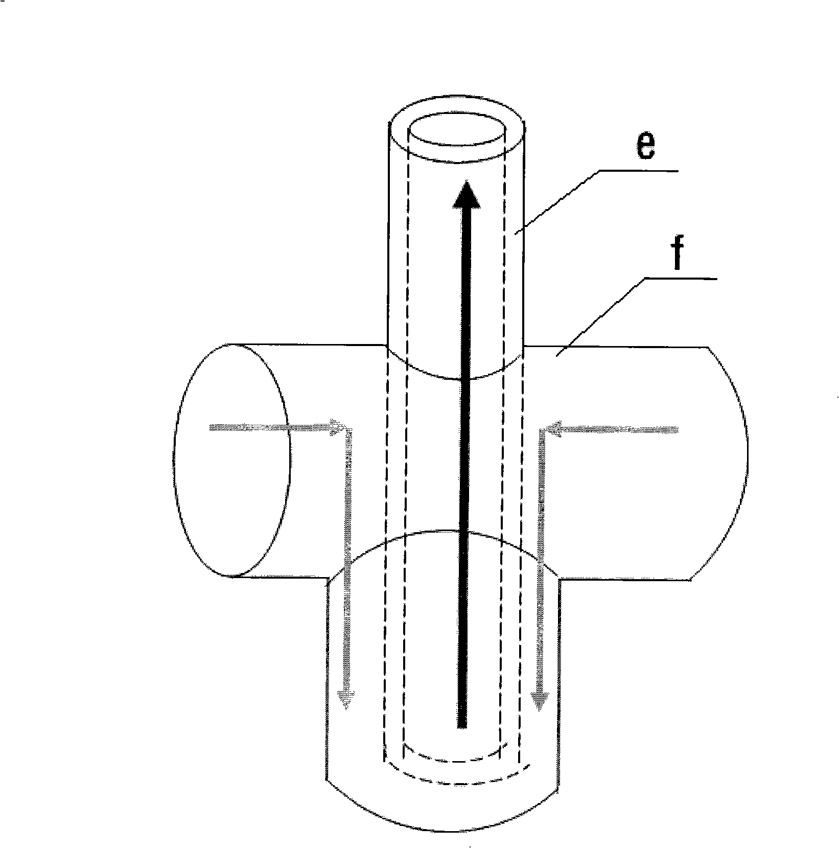
[0024] combined with Figure 2-4 , to further describe the present invention:

[0025] (1) Utilize a large drilling rig to drill a deep well with a diameter of 10 inches;

[0026] (2) stop drilling when the measured formation temperature reaches 40 degrees by logging equipment, and measure the well depth;

[0027] (3) Replace the 7-inch drill bit and continue drilling down;

[0028] (4) stop drilling when the measured formation temperature reaches 75-80 degrees, and measure the well depth;

[0029] (5) Calculate the length of the 7-inch well depth and the length of the 10-inch well depth;

[0030] (6) Lower the 7-inch casing to the bottom of the well, with a length of about 1000-1600 meters;

[0031] (7) At the same time, the 1-inch casing with thermal insulation protection layer reaches the junction of 10 inches and 7 inches, and the length is about 1,000 meters;

[0032] (8) Carry out cementing work at the bottom of the well; (9) Carry out cementing work at the upper we...


PUM


Abstract

The invention relates to a heating method of deep geothermal renewable energy sources in winter, which is pollution-free, zero-emission, clean, renewable and low-cost. The technical scheme comprises drilling a deep well under the ground, driving sleeve pipes, insulation treating for the sleeve pipes in a non-effective heating depth area under the well, employing circulating water to collect heat energy contained in underground deep rock in an effective heating depth area through the walls of the sleeve pipes, and employing insulation suction pipes to transmit the heat energy to the ground through water circulation to heat targeted users, after radiation, returning low-temperature water to underground via the insulation suction pipes, and collecting the heat energy contained in underground deep rock in the effective heating depth area through the walls of the sleeve pipes again to form a circulating heating system. The heating method for winter has the advantage that the heating method can realize zero-emission, is renewable with extremely low running cost and simple operation, and can benefit people for a lifetime after once investment. The heating method is a key breakthrough of the present heating and energy-saving method, which can largely ease the present supplying situation of winter heating energy, and really realizes energy conservation and emission reduction.

Description

1. Technical field: [0001] The invention relates to a new energy heating application technology, in particular to a pollution-free, zero-emission, clean, renewable and low-cost deep-layer geothermal renewable energy winter heating method. 2. Background technology: [0002] In the current field of geothermal energy development and utilization of dry hot rocks in the deep crust, the thermodynamic research on using water to flow in the deep well casing to extract low-grade heat energy (40-80 degrees) from the deep crust for heating is due to high cost, complicated technology, and small scope of application. (It can only be used for heating in winter, and it cannot be used for power generation) Therefore, thermodynamic research institutions all over the world have not studied this in depth. [0003] At present, the room temperature control in general buildings in developed countries mainly relies on heat pump technology to achieve heating and cooling. The energy-saving benefits ...

Claims


Application Information

Patent Timeline
IPC IPC(8): F24D3/18
CPCY02E10/10Y02B30/12Y02B10/40
Inventor 赵铭
Owner 赵铭
Why Eureka
Eureka Blog
Learn More