
Creepage breaker

A leakage circuit breaker, current transformer technology, applied in the direction of circuit devices, emergency protection circuit devices, electrical components, etc., can solve the problems of poor electromagnetic compatibility and anti-interference performance, and achieve the effect of low efficiency and suppression of interference signals

Active Publication Date: 2011-05-25
ZHEJIANG PEOPLE ELE APPLIANCE
View PDF2 Cites 0 Cited by
  • Summary
  • Abstract
  • Description
  • Claims
  • Application Information

AI Technical Summary

Problems solved by technology

[0004] The disadvantage of the above-mentioned prior art is: the electromagnetic compatibility and anti-interference performance of the existing earth leakage circuit breaker is poor

Method used


Image

  • Creepage breaker
  • Creepage breaker

Examples


Embodiment 1

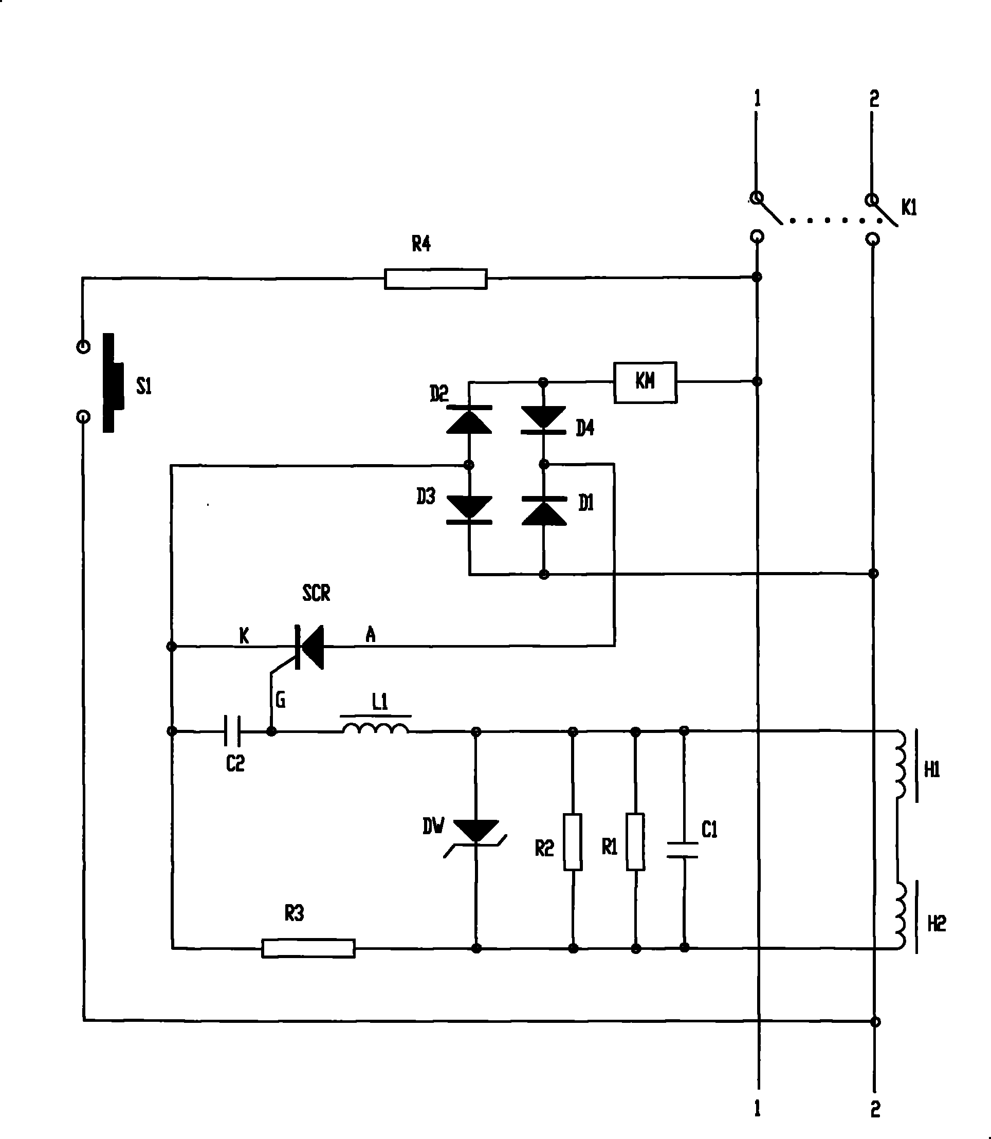
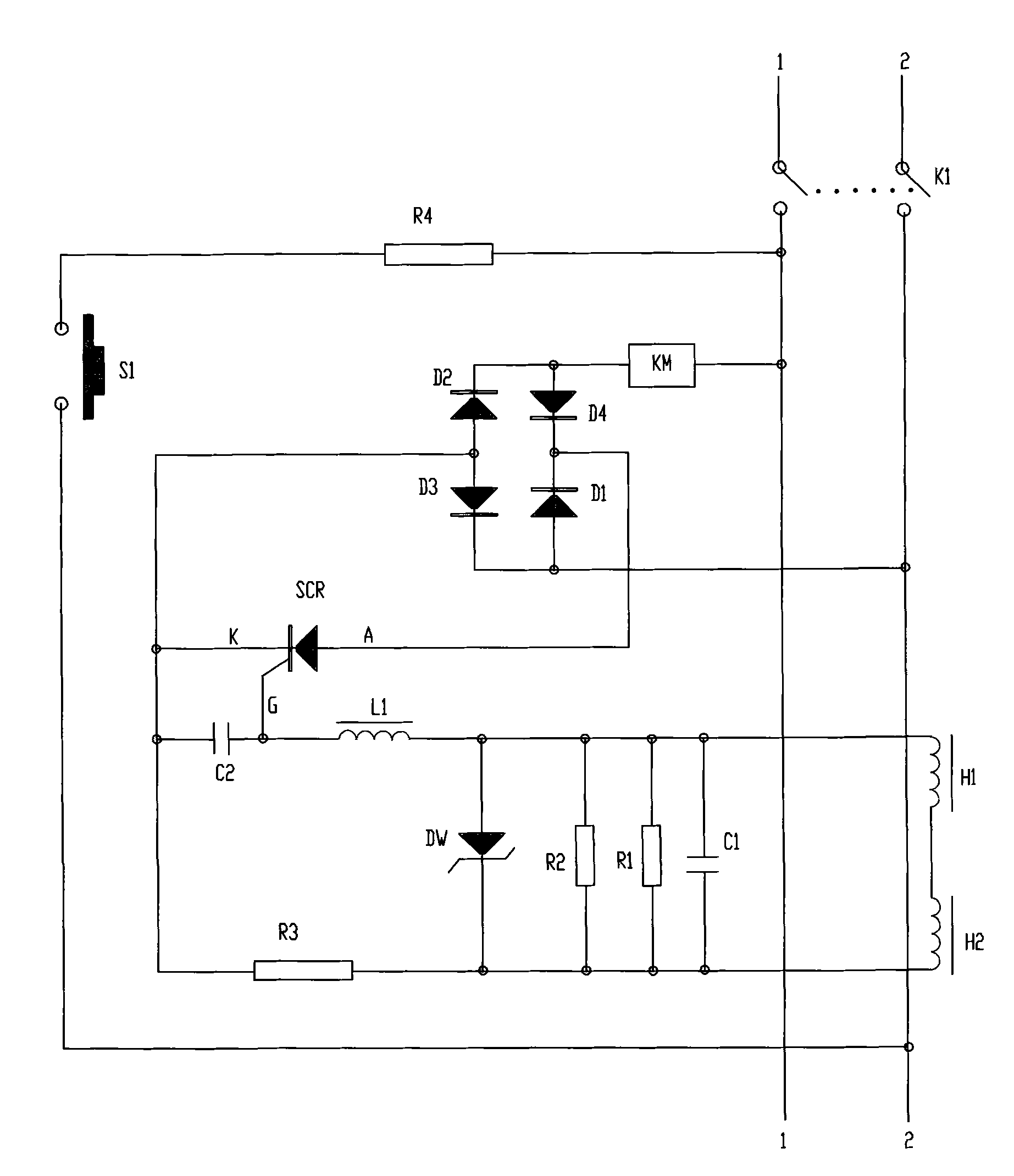
[0013] See figure 1 , the leakage circuit breaker of this embodiment includes: a bridge rectifier circuit (comprising diodes D1, D2, D3 and D4) connected to the AC power supply, used for setting on the AC power supply line (ie figure 1 The mechanical trip switch K1, the one-way thyristor SCR, the avalanche regulator DW, the low-pass filter circuit, and the resonant capacitor C1 used to detect the leakage signal of the AC power supply A parallel resonant circuit formed by a current transformer H1 and a second current transformer H2.

[0014] The electromagnet coil KM of the mechanical trip switch K1 is located in the circuit of the AC end of the bridge rectifier circuit; the low-pass filter circuit is connected with the G pole of the one-way thyristor SCR; Among them, the low-pass filter circuit includes: a second capacitor C2, a third resistor R3, and a magnetic bead L1 arranged between the anode of the avalanche regulator DW and the G pole of the one-way thyristor SCR; the s...


PUM


Abstract

The invention relates to a residual current circuit breaker in order to solve the technical problem of bad electromagnetic compatibility anti-jamming performance of the residual current circuit breaker in the prior art. The residual current circuit breaker comprises a bridge-type rectification circuit connected with an ac power supply, a mechanical tripping switch and unidirectional silicon controlled rectifier arranged in the ac power line and a parallel resonance circuit formed by a resonant capacitor and a first current transformer for testing the ac power supply. An electromagnet coil of the mechanical tripping switch is arranged in the circuit of the ac end in the bridge-type rectification circuit. A pole and K pole of the unidirectional silicon controlled rectifier respectively connect with the positive terminal and the negative terminal of the bridge-type rectification circuit and the G pole connects with the parallel resonance circuit with a resonance frequency of 50Hz.

Description

technical field [0001] The invention relates to a leakage circuit breaker, in particular to a 30mA leakage circuit breaker conforming to the GB14048.2-2001 standard. Background technique [0002] Chinese patent document CN2354282Y discloses a display-type household zero-break leakage circuit breaker, which is composed of a main control circuit, a comparison circuit, a test circuit, etc., and the main control circuit and the thyristor are all connected in parallel with varistors. [0003] Chinese patent document CN2276678Y discloses a single-phase zero-break leakage protector. An OR gate circuit is added to the leakage protector with a sequential electrical connection structure of a mechanical trip switch electromagnet coil, a one-way thyristor element, and a diode, so that the OR gate The two diodes in series in the circuit are electrically connected to the one-way thyristor element and the electromagnet coil of the mechanical trip switch according to the same conduction dir...

Claims


Application Information

Patent Timeline
Patent Type & Authority Patents(China)
IPC IPC(8): H02H3/32
Inventor 黄东海陈双龙任海波
Owner ZHEJIANG PEOPLE ELE APPLIANCE
Learn More