
Gas distribution device and plasma processing apparatus applying the same

A gas distribution and gas technology, applied in the field of ions, can solve the problems of short service life of the gas distribution device, easy breakage during disassembly and cleaning, and high requirements for parts processing accuracy, and achieves the effects of simple structure, easy disassembly and assembly, and low accuracy requirements.

Active Publication Date: 2009-01-07
BEIJING NAURA MICROELECTRONICS EQUIP CO LTD
View PDF0 Cites 42 Cited by
  • Summary
  • Abstract
  • Description
  • Claims
  • Application Information

AI Technical Summary

Problems solved by technology

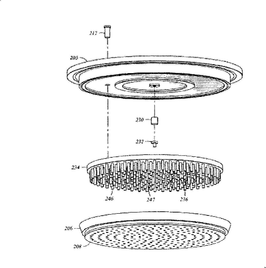
[0009] Although the above-mentioned gas distribution device can distribute gases such as process gases to enter the reaction chamber, in practical applications, the processing of this gas distribution device is relatively difficult, and it is relatively difficult to assemble, use, disassemble and clean. It is prone to breakage and other damage, which makes the service life of the gas distribution device short
In addition, because the structure of the above-mentioned gas distribution device is relatively complicated, the processing precision of the parts is required to be high, and the processing is difficult, so the processing cost is relatively high

Method used


Image

  • Gas distribution device and plasma processing apparatus applying the same
  • Gas distribution device and plasma processing apparatus applying the same
  • Gas distribution device and plasma processing apparatus applying the same

Examples


Embodiment Construction

[0051] The technical scheme of the gas distribution device provided by the present invention and the plasma processing equipment applying the gas distribution device will be explained in detail below with reference to the accompanying drawings.

[0052] Before describing the gas distribution device provided by the present invention in detail, it may be specified that the back side of the present invention is the side of each component facing the reaction chamber, and correspondingly, the front side of each component is the side of each component facing away from the reaction chamber. It can also be inferred that the side facing the back of each component of the gas distribution device provided by the present invention is the lower side, and the side facing the front is the upper side.

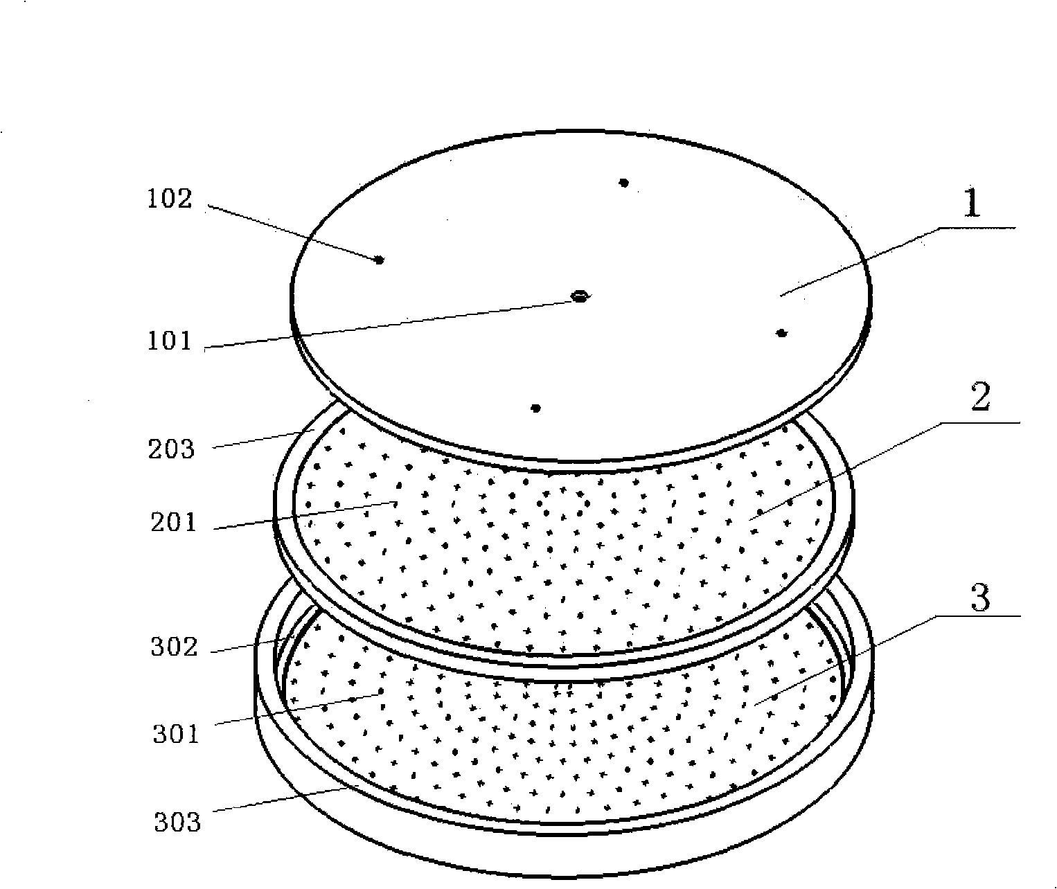
[0053] See image 3 , The gas distribution device provided by the present invention includes a support plate 1, a baffle plate 2, and a shower head electrode 3 which are sequentially stacked from t...


PUM


Abstract

The invention discloses a device used for distributing gases, comprising a support plate, a baffle and a spray header electrode; the support plate is provided with an air inlet passage, and the spray header electrode is provided with an exhaust passage. The back of the support plate is provided with a first support table and stream guiding bosses of the support plate, and stream guiding grooves are formed among the stream guiding bosses as well as between the first support table and the stream guiding bosses; the front surface of the baffle is provided with a second support table to superpose the support plate and the baffle together, at the same time, the gas coming from the air inlet passage can be transferred and spread by the stream guiding grooves; through holes of the baffle are arranged on the baffle to lead the gas coming from the stream guiding grooves to be transferred above the spray header electrode, and the gas can be discharged out into a reaction chamber by the exhaust passage. The invention also discloses a plasma treatment device. The device of the invention can evenly distribute the gases, and has the advantages of simple structure, low cost, being convenient for processing and maintaining, as well as being not easy to be damaged.

Description

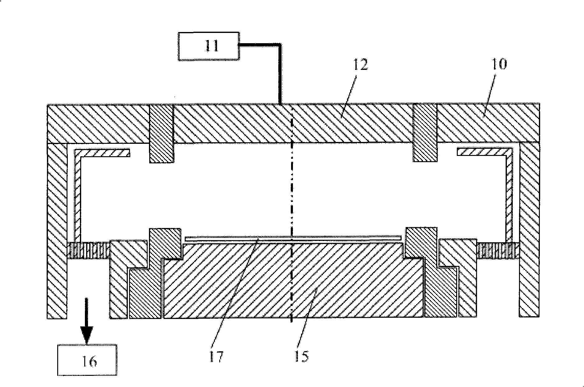
Technical field [0001] The present invention relates to the field of plasma technology, and in particular to a gas distribution device and a plasma processing equipment using the gas distribution device. Background technique [0002] With the development of science and technology, plasma technology has been widely used, for example, it can be applied to many plasma processing equipment such as integrated circuit processing equipment, solar equipment and flat panel display equipment. [0003] figure 1 A common parallel plate plasma processing equipment is shown, which includes a reaction chamber 10, an upper electrode 12, a lower electrode 15, a gas input system 11, a vacuum obtaining system 16, and the like. Wherein, the upper electrode 12 and the lower electrode 15 are respectively connected to one or more power sources with different frequencies, and the workpiece 17 to be processed / processed is placed on the lower electrode 15. [0004] The process of the plasma processing e...

Claims


Application Information

Patent Timeline
Patent Type & Authority Applications(China)
IPC IPC(8): H01L21/00H01L21/02C23C16/455C23F4/00H01J37/32H05H1/00
Inventor 宋巧丽南建辉
Owner BEIJING NAURA MICROELECTRONICS EQUIP CO LTD
Learn More