Direct sulfuration device of radial parting mold of radial ply tyre
A radial tire and flexible mold technology, which is applied in the field of direct vulcanization equipment for radial tire flexible molds, can solve the problems of low production efficiency and long locking time, and achieve the effects of simple structure, good locking effect and reduced lifting force
- Summary
- Abstract
- Description
- Claims
- Application Information
AI Technical Summary
Problems solved by technology
Method used
Image
Examples
Embodiment 1
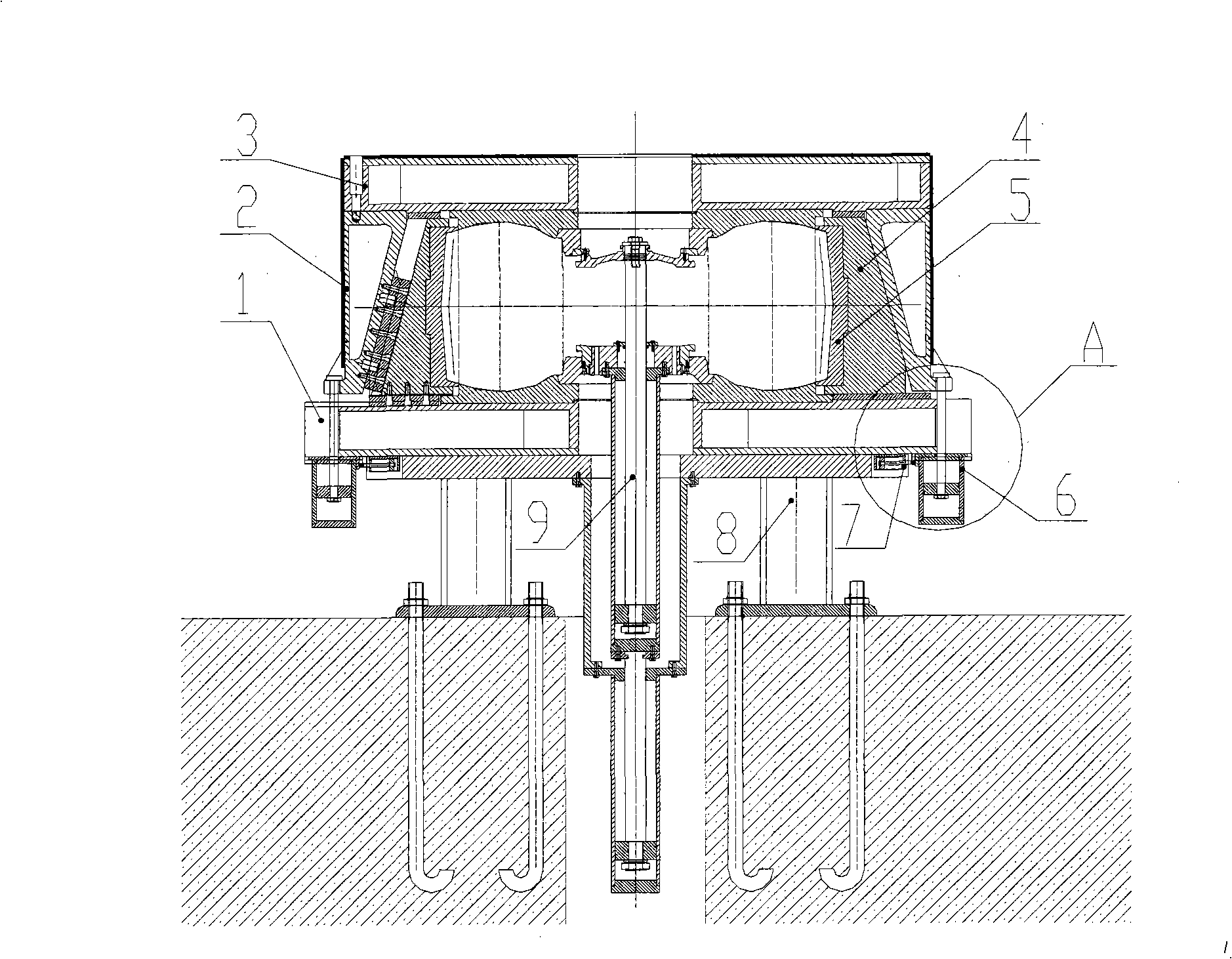
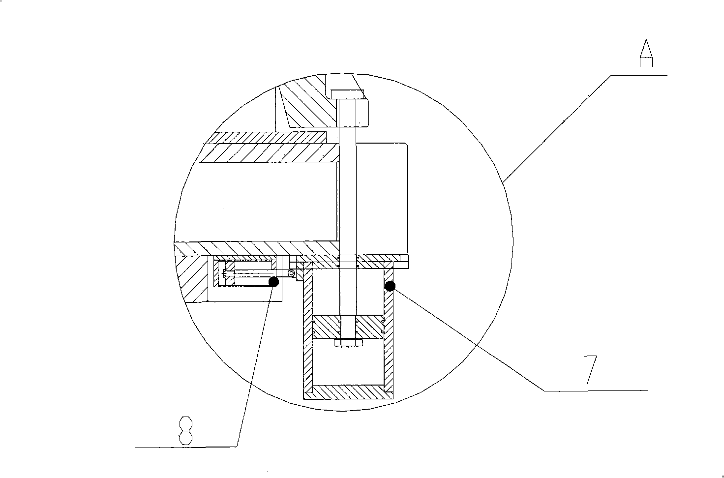
[0033] Such as figure 1 with figure 2As shown, the horizontally installed radial action cylinder 7 is connected to the locking hydraulic cylinder 6 through its piston rod, the locking hydraulic cylinder 6 and the radial action cylinder 7 are evenly distributed along the circumferential direction of the outer edge of the bottom surface of the lower bottom plate 1, and the locking hydraulic pressure The top of the piston rod of the cylinder 6 is provided with a protrusion, and an opening groove is provided corresponding to the circumference of the protruding part of the lower edge of the middle die sleeve 2. The protrusion is located above the opening groove, and the locking hydraulic cylinder 6 provided therein and radial action The number of cylinders 7 is ten. The upper cover plate 3, the lower bottom plate 1 and the middle mold case 2 are respectively provided with steam chambers, and steam is passed into the steam chambers to complete the heating and vulcanization of the ...
Embodiment 2
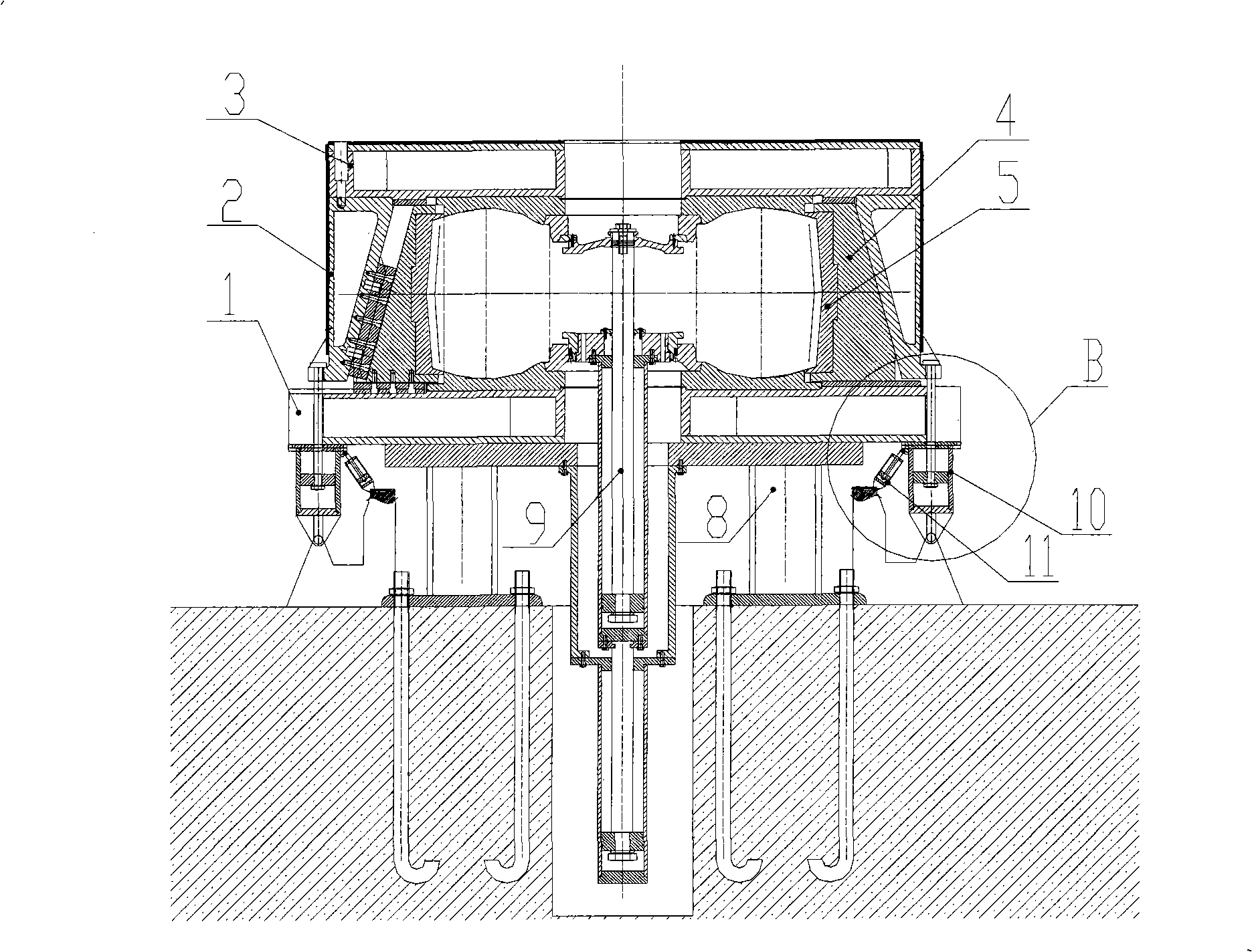
[0038] exist image 3 with Figure 4 In the shown direct vulcanization equipment, the hydraulic locking device is composed of a swing lock hydraulic cylinder 10 and a swing action cylinder 11. The tails of the swing lock hydraulic cylinder 10 and the swing action cylinder 11 are hinged on the base, and the swing lock The swing of the hydraulic cylinder 10 around the hinge point is controlled by the swing cylinder 11. When the swing locking hydraulic cylinder 10 is in the vertical position, the projection on the top of the piston rod is pressed on the opening groove under the pulling of the piston rod, controlling the clamping and locking of the mould. When the swing locking hydraulic cylinder 10 is in the outwardly tilted position, the mold can be opened.
[0039] Others are the same as embodiment 1.
Embodiment 3
[0041] exist Figure 5 with Image 6 Among them, the hydraulic locking device is a locking hydraulic cylinder 12 whose piston rod can rotate 90 degrees in the horizontal direction. The top of the piston rod of the locking hydraulic cylinder 12 is provided with a bump. When the piston rod is tightened downwards to close the mold, the bump is just stuck on the opening groove provided on the lower outer edge of the middle mold sleeve 2, and the piston rod pushes the middle mold. The sleeve 2 is pulled down to realize mold clamping and locking. When the mold is opened, the piston rod of the locking hydraulic cylinder 12 first rises for a short distance, rotates 90 degrees, and then descends while pulling the protrusion to move downward. . When the mold is closed next time, the piston rod of the locking hydraulic cylinder 12 rises first after the middle die sleeve 2 drops to a certain position. The piston rod is reversely rotated 90 degrees, and then tightened downward. When th...
PUM
 Abstract
Description
Claims
Application Information
 - Generate Ideas
- Intellectual Property
- Life Sciences
- Materials
- Tech Scout
- Unparalleled Data Quality
- Higher Quality Content
- 60% Fewer Hallucinations
Browse by: Latest US Patents, China's latest patents, Technical Efficacy Thesaurus, Application Domain, Technology Topic, Popular Technical Reports.
© 2025 PatSnap. All rights reserved.Legal|Privacy policy|Modern Slavery Act Transparency Statement|Sitemap|About US| Contact US: help@patsnap.com


