
Method and apparatus for applying a layer of a separating agent to a substrate

A separation agent and substrate technology, which is applied to the device, coating, spraying device and other directions of coating liquid on the surface, can solve the problems of slow performance of the separation agent, unusable non-volatile components and decomposition products, and pollution of the vacuum chamber, etc. To achieve the effect of saving costs and solving the performance change of the separating agent

Inactive Publication Date: 2009-01-07
LEYBOLD OPTICS
View PDF1 Cites 3 Cited by
  • Summary
  • Abstract
  • Description
  • Claims
  • Application Information

AI Technical Summary

Problems solved by technology

However, since a pressure equalization hole is generally necessary, the separating agent vapor can enter the vacuum chamber at other places and contaminate the vacuum chamber
[0009] In the current separating agent evaporator, a large amount of separating agent is heated in the liquid tank, only a small part of the separating agent is evaporated during the coating process of the equipment, and the unevaporated part will continue to be used until the hard volatile components and Decomposition products cannot be used further and the evaporator must be cleaned
A disadvantage here is that the performance of the separating agent changes slowly and uncontrollably over the lifetime of the separating agent due to deposits of less volatile components and decomposition products
In addition, there is a residual liquid of separating agent that must be disposed of, which leads to waste and may be harmful to the environment

Method used


Image

  • Method and apparatus for applying a layer of a separating agent to a substrate

Examples


Embodiment Construction

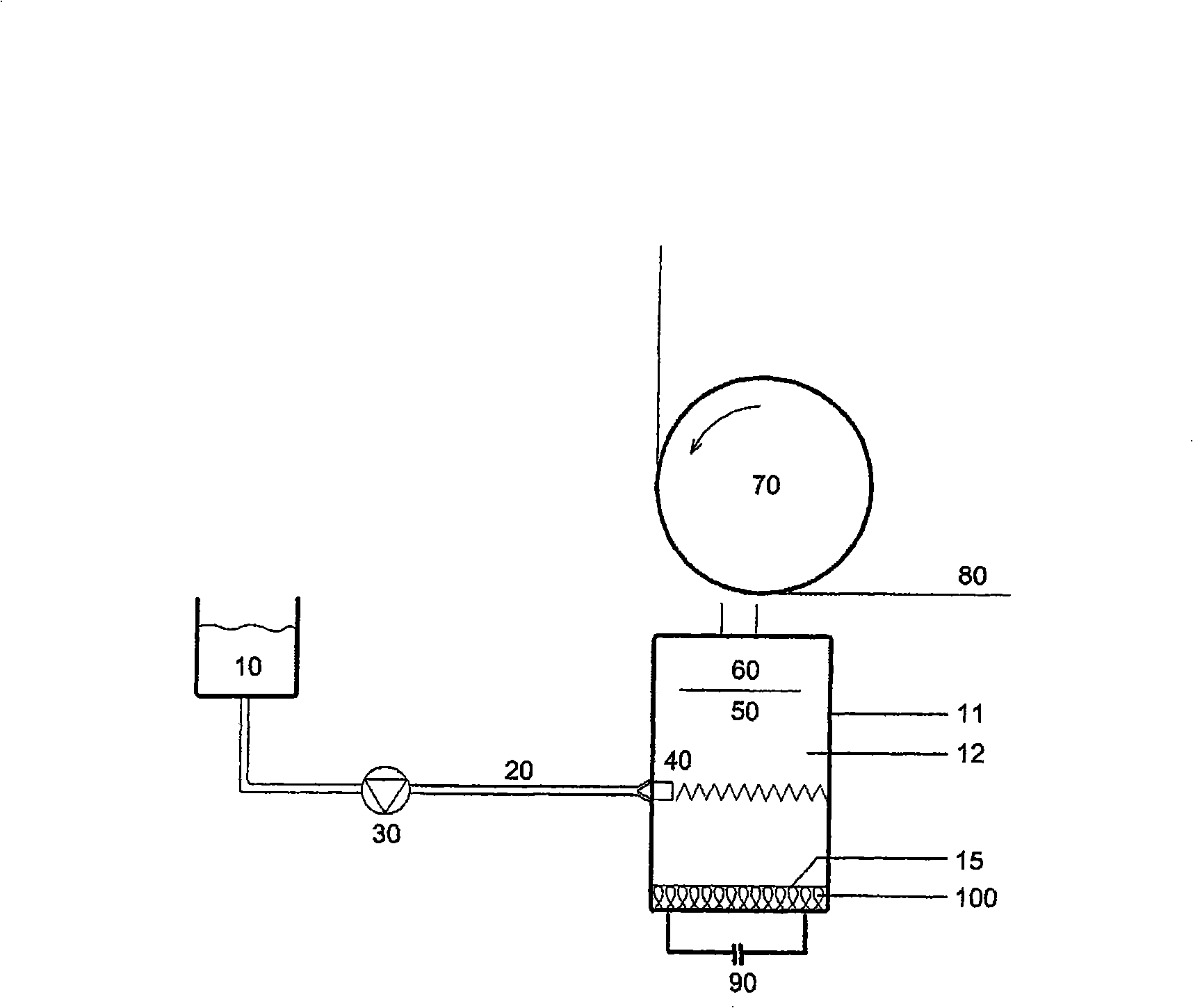
[0026] figure 1 The illustrated evaporator chamber 11 has an inner chamber 12 , which includes corresponding chamber walls, not denoted by reference numerals in the figures, and is equipped with nozzles 60 which are aimed at a moving strip-shaped substrate 80 . The nozzle 60 has an inner chamber-side opening through which the evaporated or vaporous separating agent is sprayed in the region of the substrate 80 . The substrate 80 is transported by a roller 70 arranged in the vacuum chamber of a not exactly shown coating system equipped with a metal evaporator, the direction of rotation of the roller 70 being indicated here by an arrow. Coating of aluminum is preferred, but not exclusive.

[0027] In the inner space 12 of the evaporator chamber 11 there is an evaporator plate 15 which can be heated by means of a heater 100 which is heated, for example, by means of a voltage source 90 . In addition, the chamber walls of the inner chamber 12 may be heated. In terms of location, ...


PUM


Abstract

In a method which is used for coating a separating agent layer into a moving or movable substrate in a vacuum chamber, the separating agent is evaporated in an internal chamber of evaporator chamber which is provided with at least one nozzle that is aligned to the substrate. The method orders that the liquid separating agent used for vaporizing is sprayed into the internal chamber of the evaporator chamber. In a device thereof which is used for coating the separating agent into a moving or movable substrate in the vacuum chamber, the vacuum chamber is provided with at least one metal evaporator. The device is provided with an evaporator chamber which is configured with at least one nozzle aligned to the substrate, wherein the separating agent can be delivered to the internal chamber of the evaporator chamber through the conveying pipeline. Hereon, the conveying pipeline is connected with a spraying device, and the liquid separating agent which is used for vaporizing can be sprayed or be sprayed into the internal chamber of the evaporator chamber with the spraying device.

Description

technical field [0001] The present invention relates to a method and an apparatus for coating a layer of a separating agent on a moving or movable substrate in a vacuum chamber, wherein the separating agent is to be evaporated or can be evaporated in the inner chamber of an evaporator chamber equipped with at least one nozzle directed at the substrate was evaporated. Background technique [0002] The moving or moveable substrate, usually a strip substrate, will be coated with the metal in the vacuum chamber of the coating plant. When coating, the substrate will pass through the metal coating unit, where the substrate is unwound from a take-off drum by rollers and onto a take-up drum. [0003] Separating agents may generally involve esters, glycols, fluorinated hydrocarbons, and hydrocarbons. Perfluoropolyether oils are preferred. The substrate is provided with a masking layer by applying a release agent in the so-called blank space so that no metal is applied in this area...

Claims


Application Information

Patent Timeline
Patent Type & Authority Applications(China)
IPC IPC(8): B05D7/24B05C9/08B05C11/10B05B15/04
CPCC23C14/243C23C14/246C23C14/042C23C14/562
Inventor S·库珀
Owner LEYBOLD OPTICS
Learn More