Telescoping clamp assembly

A telescopic, clamp technology, used in manufacturing tools, claw arms, manipulators, etc., to solve problems such as loosening and unintentional disassembly of clamp components

Inactive Publication Date: 2008-12-31
DELAWARE CAPITAL FORMATION
View PDF0 Cites 14 Cited by
  • Summary
  • Abstract
  • Description
  • Claims
  • Application Information

AI Technical Summary

Problems solved by technology

Therefore, loosening or adjusting the bolt - such as loosening or adjusting the end clamp - will also loosen the telescoping shaft and may result in unintentional disassembly of the clamp assembly

Method used


Image

  • Telescoping clamp assembly
  • Telescoping clamp assembly
  • Telescoping clamp assembly

Examples


Embodiment Construction

[0022] The following description is merely exemplary in nature, and is not intended to limit the disclosure, application, or use of the present invention.

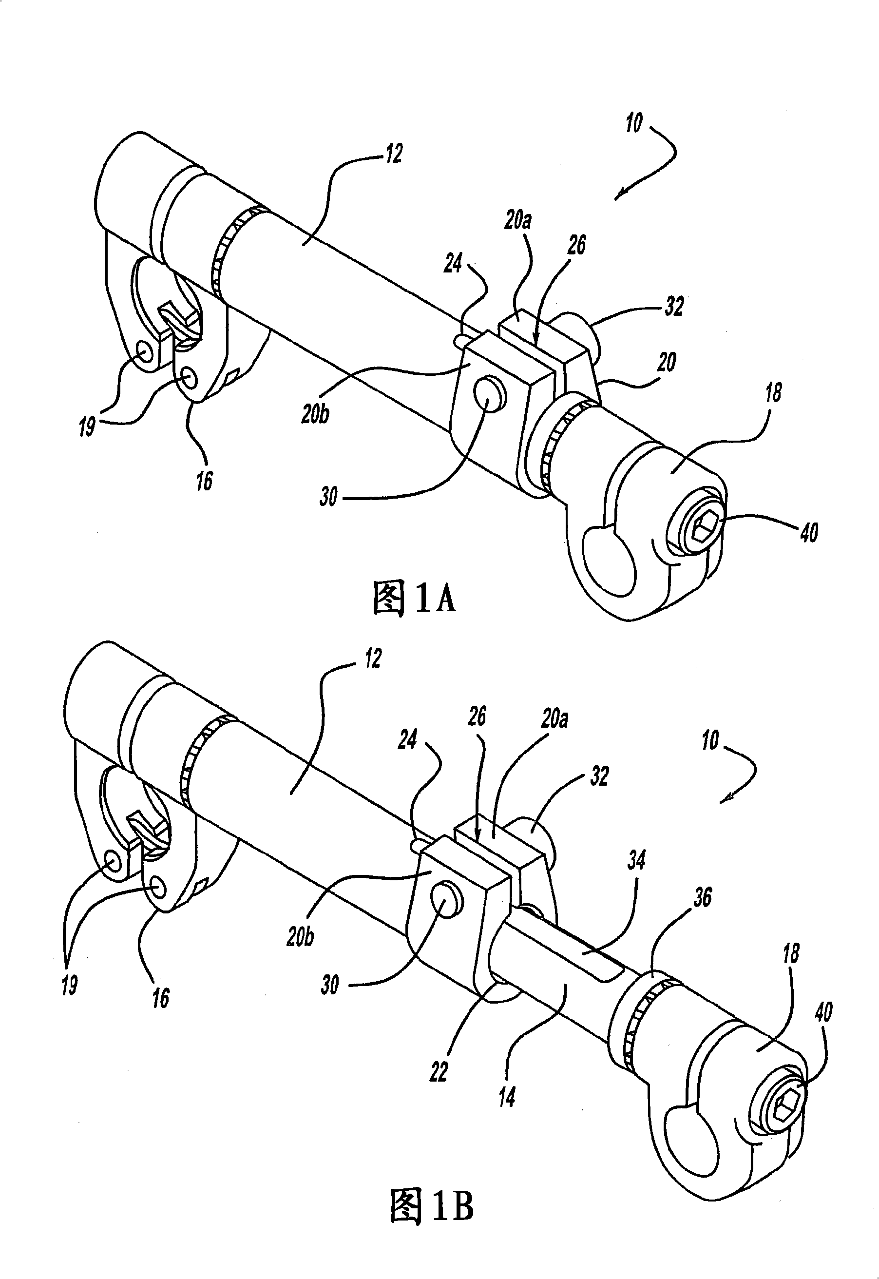
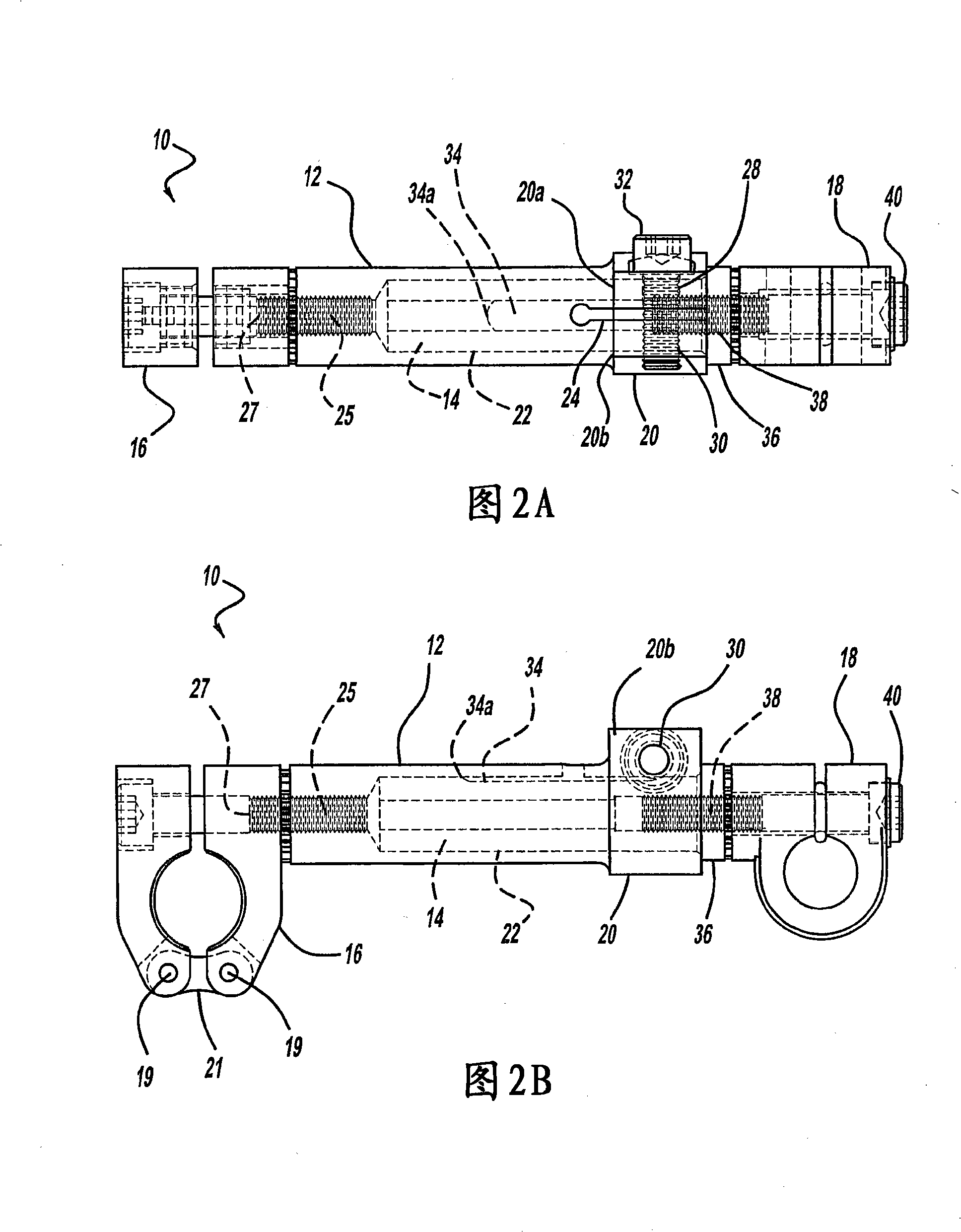
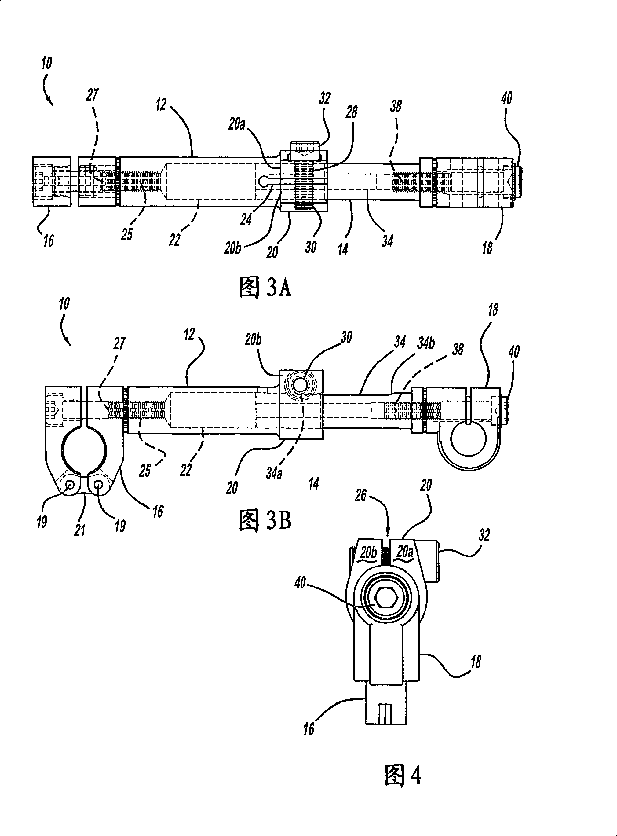
[0023] Referring now to the drawings and the exemplary embodiments illustrated therein, a telescopic clamp assembly 10 for a material handling system includes an outer shaft or tube 12 that is telescopically engaged with an inner shaft or telescopic shaft 14 (FIG. 1B ). The tube 12 and the telescopic shaft 14 can be adjusted relative to each other to adjust the length of the telescopic clamp assembly 10 between the retracted length (Figures 1A, 2A, and 2B) and the extended length (Figures 1B, 3A, and 3B). When at the required degree of extension, as will be explained below, the telescopic shaft 14 may be fixed with respect to the tube 12 via a holder, or a clamp, or a pin, or a bolt, or a fastener 32. The fastener 32 is also used to restrict the inner shaft from extending and / or pulling out of the outer shaft, which will be de...


PUM


Abstract

A telescoping clamp assembly for a material handling system includes an inner shaft, an outer shaft, a clamping device, and a retaining element. The inner shaft has a longitudinal guide portion along an outer surface of the inner shaft. The outer shaft has a bore adapted to receive the inner shaft. The clamping device is located at the outer shaft and is configured to tighten the outer shaft about the inner shaft. The retaining element is adjustable to adjust a degree of clamping of the clamping collar at the outer shaft. The retaining element also engages the longitudinal guide portion of the inner shaft to limit extension and / or extraction of the inner shaft from the outer shaft.

Description

[0001] Cross-references to related applications [0002] This application claims the priority of U.S. Provisional Application No. 60 / 917,786 filed on May 14, 2007. The disclosure of the above-mentioned application is incorporated herein by reference. Technical field [0003] The present invention mainly relates to a material processing system, and more specifically, to an adjustable clamp used to clamp or install a device to a supporting structure of the material processing system. Background technique [0004] Automated material handling systems such as manipulators are mainly used to move target objects within and / or between manufacturing stages in the manufacturing process. Typical objects that can be moved during or between production processes include, for example, glass windows, thin metal sheet stampings, separate parts to be welded, bolted or otherwise connected to each other, or to be connected to larger components Partial assembly. In consideration of the adaptability an...

Claims


Application Information

Patent Timeline
IPC IPC(8): B25J17/00B25J18/02B25J19/00
Inventor 莫里斯·佩尔曼
Owner DELAWARE CAPITAL FORMATION
Why Eureka
Try Eureka