Full automatic stone slab edger unit

A technology for edging equipment and stone plates, which can be used in grinding/polishing equipment, metal processing equipment, machine tools suitable for grinding workpiece edges, etc., and can solve problems such as unevenness, poor grinding quality, and unstable clamping. , to achieve the effect of stable operation, good grinding quality and stable clamping

Inactive Publication Date: 2008-12-31
李 新杰
View PDF0 Cites 6 Cited by
  • Summary
  • Abstract
  • Description
  • Claims
  • Application Information

AI Technical Summary

Problems solved by technology

In the prior art, the stone slab edging equipment has the following problems: 1. Most of the stone slabs can only be placed horizontally, but cannot be clamped vertically, especially cannot be clamped vertically and drive it to move back and forth, because the fixation is not enough. The thickness of the slate that can be clamped by the movable clamping mechanism is determined by the size of the gap between the clamping parts. Uniform, that is, the thickness of some parts is slightly larger, while the thickness of some parts is slightly thinner, so when the stone plate clamped vertically moves back and forth relative to the clamping parts, the fixed gap between the clamping parts is difficult to adapt to the stone plate The thickness variation of different parts makes the clamping unstable, the operation of the stone plate is unstable, and the grinding quality is poor

Method used


Image

  • Full automatic stone slab edger unit
  • Full automatic stone slab edger unit
  • Full automatic stone slab edger unit

Examples


Embodiment 1

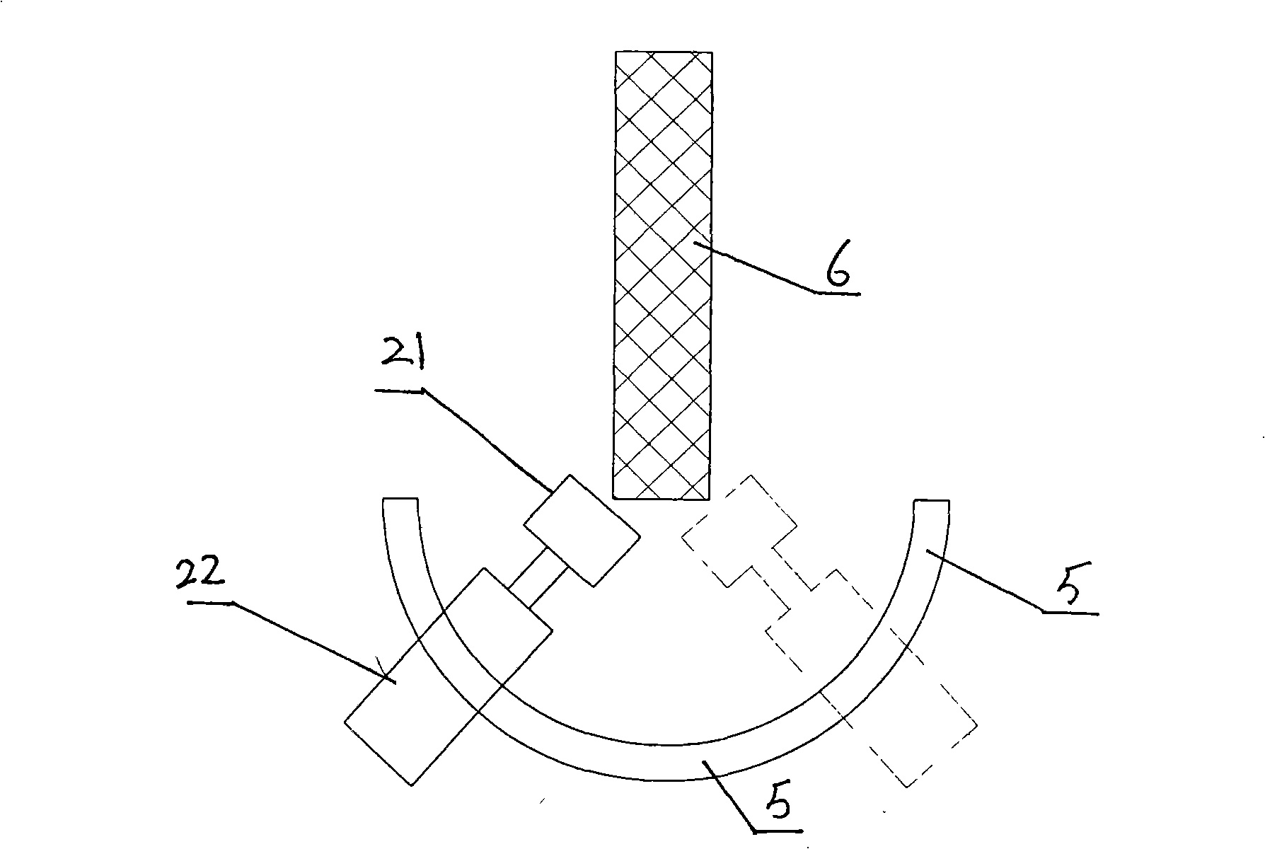
[0019] figure 1 , figure 2 The shown automatic stone slab edging equipment includes a frame 1, on which a grinder and a clamping drive mechanism are installed, the grinder is installed below the clamping drive mechanism, and the grinder includes a grinding wheel 21 and The motor 22 that drives the grinding wheel to rotate at a high speed; the clamping drive mechanism includes two rows of vertically installed clamping rollers, wherein the support of the first row of clamping rollers 3 is fixedly installed on the frame, and the first row of clamping rollers 3 A drive motor is provided, the first row of clamping rollers is a metal roller, and the inner side of the first row of clamping rollers is cushioned with a rubber conveyor belt 31 . The second row of clamping rollers 4 is a rubber pressure roller, and the support of the rubber pressure roller 4 can be mounted on the frame in a horizontally sliding manner, and a lateral thrust cylinder 41 is provided corresponding to the s...


PUM


Abstract

A fully automatic stone slab edger unit comprises a frame; the frame is provided with a milling machine and a clamp drive mechanism; the milling machine is arranged under the clamp drive mechanism; the clamp drive mechanism comprises two rows of gripping rolls which are vertically arranged, wherein, a bracket of the first row of the gripping rolls is arranged at the frame; the second row of the gripping rolls are rubber pressure rolls; a bracket of each rubber pressure roller is movably arranged at the frame in the manner of a cross slip; a bracket corresponding to each rubber pressure roll is provided with a transverse thrust cylinder; a piston rod of the transverse thrust cylinder is fixedly connected with the bracket of the rubber pressure rolls. The fully automatic stone slab edger unit of the invention can vertically clamp a stone slab and drive the stone slab to move back and forth, has firm gripping, and causes the stone slab to move stably.

Description

technical field [0001] The invention belongs to the technical field of stone plate processing, and in particular relates to a fully automatic stone plate edge grinding equipment. Background technique [0002] Stone slab edging equipment includes a grinding machine and a clamping drive mechanism. The grinder includes a grinding wheel and a motor that drives the grinding wheel to rotate at high speed. The function of the clamping drive mechanism is mainly to clamp the stone slab and drive the stone slab to move back and forth. . In the prior art, the stone slab edging equipment has the following problems: 1. Most of the stone slabs can only be placed horizontally, but cannot be clamped vertically, especially cannot be clamped vertically and drive it to move back and forth, because the fixation is not enough. The thickness of the slate that can be clamped by the movable clamping mechanism is determined by the size of the gap between the clamping parts. Uniform, that is, the t...

Claims


Application Information

Patent Timeline
Patent Type & Authority Applications(China)
IPC IPC(8): B24B9/06
Inventor 李新杰
Owner 李 新杰
Why Eureka
Try Eureka