
Gas film quick continuous casting device and method in magnetostatic field

A technology of static magnetic field and gas film, which is applied in the field of metallurgy, can solve the problems of no obvious increase in casting speed, expensive porous graphite ring, and affecting the quality of cast billets, so as to ensure uniformity and stability, facilitate processing, and improve surface quality. quality effect

Inactive Publication Date: 2008-12-31
NORTHEASTERN UNIV
View PDF1 Cites 31 Cited by
  • Summary
  • Abstract
  • Description
  • Claims
  • Application Information

AI Technical Summary

Problems solved by technology

However, the crystallizer in the continuous casting equipment is the core equipment, and its structure has always been a confidential technology. The existing literature "The airslip casting mold-an established technology" (J.P.Faunce, Light metals 1985) and "Improved technology of the AIRSOLVEIL billet casting system" (W.Schneider, Light Metals 1994) can only see its structure diagram
[0003] Domestic patent CN1621179 "Aluminum Alloy Vapor Film Continuous Casting Crystallizer", document "Experimental Research on Soft Contact Vapor Film Continuous Casting" (Luo Hongbo et al., Journal of Shanghai University, 2002, Volume 8, No. 5) all have a comprehensive understanding of VFC technology There are detailed introductions, but the domestic air film casting technology is either still in the experimental stage, or uses porous graphite rings. billet quality
[0004] Due to the influence of the stability of the gas film in the existing technology, the casting speed of the two technologies is not significantly improved compared with the traditional hot top casting, and the fast and efficient continuous casting technology has always been the pursuit of metallurgists

Method used


Image

  • Gas film quick continuous casting device and method in magnetostatic field
  • Gas film quick continuous casting device and method in magnetostatic field
  • Gas film quick continuous casting device and method in magnetostatic field

Examples


Embodiment 1

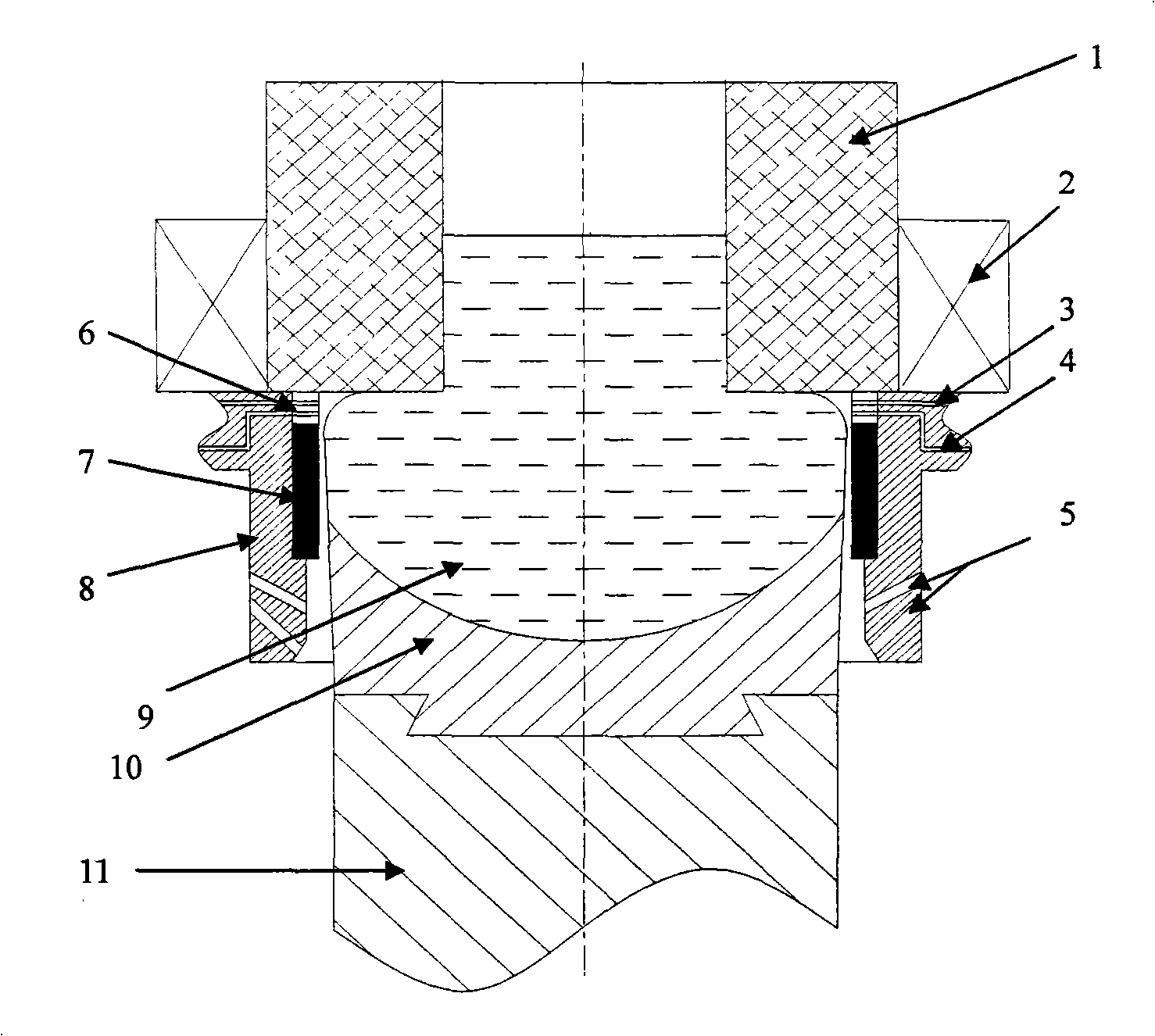
[0019] Gas film rapid continuous casting device such as figure 1 As shown, the hot top is surrounded by an induction coil, and an oil and gas ring is arranged between the outlet of the hot top and the graphite ring. The material is austenitic stainless steel. The oil and gas ring is provided with oil inlet and air inlet holes, and the oil inlet and The air inlet can pass oil and gas from the outside of the crystallizer to the crystallizer through the oil and gas channels on the crystallizer; the outside of the oil-gas ring and the graphite ring are connected to the crystallizer, and the crystallizer is provided with a double at the lower part of the joint with the graphite ring. The angle between the upper cooling water channel and the crystallizer wall is 60°, and the angle between the lower cooling water channel and the crystallizer wall is 30°.

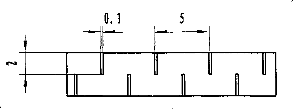
[0020] The oil and gas ring of the present invention is such as figure 2 As shown, the oil inlet holes and the air inlet holes are ...


PUM

PropertyMeasurementUnit
magnetic flux densityaaaaaaaaaa

Abstract

The invention discloses a rapid gas film continuous casting device under the action of a magnetostatic field; the device comprises a crystallizer, a hot top, an induction coil, a double-layer cooling water channel, an oil-gas ring and a graphite annulus, and is characterized in that the hot top is surrounded by the induction coil, the oil-gas ring is arranged between the outlet of the hot top and the graphite annulus, the oil-gas ring is provided with an oil inlet and a gas inlet, the oil inlet and the gas inlet can lead oil and gas outside the crystallizer to the crystallizer by an oil channel and a gas channel on the crystallizer; lubricant and gas are led to the oil-gas ring in the rapid gas film continuous casting; the magnetic field is applied by the induction coil, and an alloy is poured at the pouring temperature. The rapid gas film continuous casting device can obviously improve the surface quality and inherent metallurgical quality of ingot casting, and improve throwing speed and production efficiency.

Description

Technical field [0001] The invention belongs to the technical field of metallurgy, and particularly relates to a gas film rapid continuous casting device and method under the action of a static magnetic field. Background technique [0002] The gas film continuous casting technology is to form a layer of gas film between the inner wall of the mold and the casting slab, so that the inner wall of the mold and the ingot are in soft contact, which not only reduces the friction between the slab and the mold, but also Improve the surface quality. In the existing technology, there are two ways to form a gas film between the mold and the billet. One is the American AIRSLIP continuous casting technology, and the other is the German AIRSOL VEIL continuous casting technology. The difference between the two technologies is The reason is that the former uses a high-quality porous graphite ring to inject oil and gas into the inner wall of the crystallizer, while the latter uses a gap between th...

Claims


Application Information

Patent Timeline
Patent Type & Authority Applications(China)
IPC IPC(8): B22D11/00B22D11/18B22D11/11B22D11/112B22D11/115
Inventor 崔建忠屈福赵志浩左玉波张海涛朱庆丰
Owner NORTHEASTERN UNIV
Learn More