Ultrasonic wave nondestructive apparatus and method for measuring residual stress of welded structure
A technology for residual stress and welded structures, which is applied in the analysis of solids using sound waves/ultrasonic waves/infrasonic waves, and can solve problems such as damage to workpieces, inability to meet residual stress measurements of welded structures, and time-consuming problems
- Summary
- Abstract
- Description
- Claims
- Application Information
AI Technical Summary
Problems solved by technology
Method used
Image
Examples
specific Embodiment approach 1
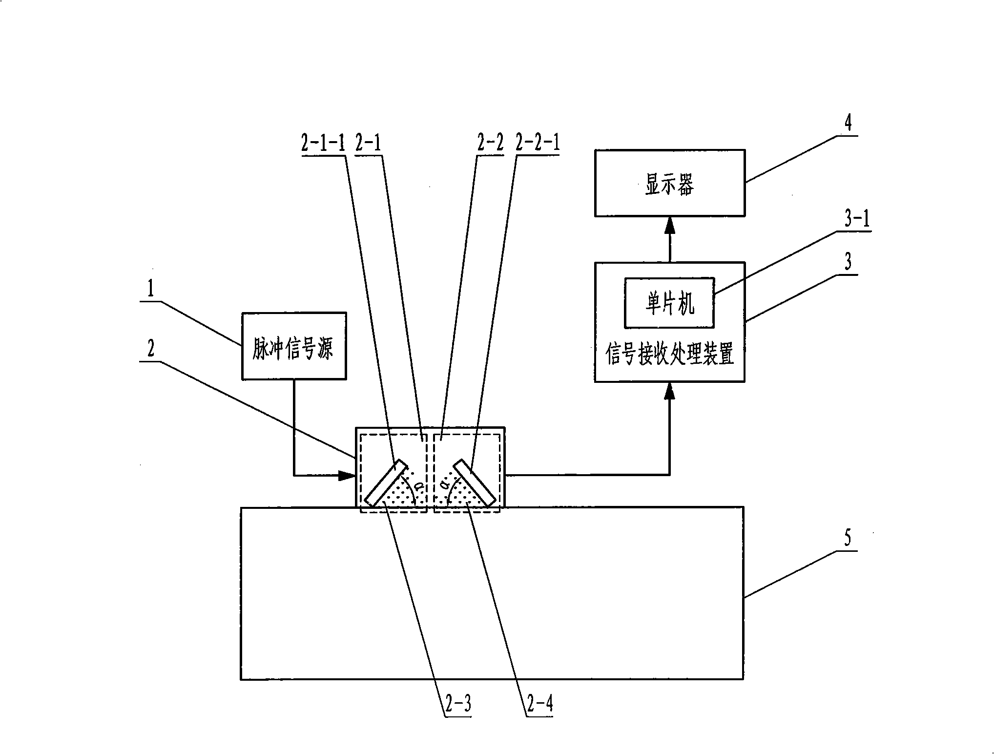
[0050] Specific implementation mode one: the following combination figure 1 Describe this embodiment, this embodiment is made up of pulse signal source 1, probe group 2, signal receiving and processing device 3 and display 4, the output terminal of pulse signal source 1 is connected with the transmitting terminal 2-1 of probe group 2, and probe group 2 The receiving terminal 2-2 of the signal receiving and processing device 3 is connected to the input end, the output end of the signal receiving and processing device 3 is connected to the display 4, and the signal receiving and processing device 3 is embedded with a single chip microcomputer 3-1.
[0051] The display 4 displays the waveform received by the signal receiving and processing device 3 .
specific Embodiment approach 2
[0052] Specific implementation mode two: the following combination Figure 7 , Figure 8 , Figure 9 To illustrate this embodiment, the ultrasonic non-destructive measurement method implemented based on the device described in Embodiment 1 includes the following steps:
[0053] Step a: Determine the coordinates of the measuring point (x i ,y i ), read in or manually input the coordinates of the measuring point (x i ,y i ) and output to the signal receiving and processing device 3, wherein i is the subscript of the measuring point coordinates;
[0054] Step b: The transmitting terminal 2-1 of the probe group 2 injects the pulse signal emitted by the pulse signal source 1 into the workpiece 5 through the first propagation medium 2-3 at the first critical refraction angle, and then the critical refraction longitudinal wave generated is transmitted to the workpiece 5 in the spread;
[0055] Step c: Read the envelope data of the critical refraction longitudinal wave propagat...
specific Embodiment approach 3
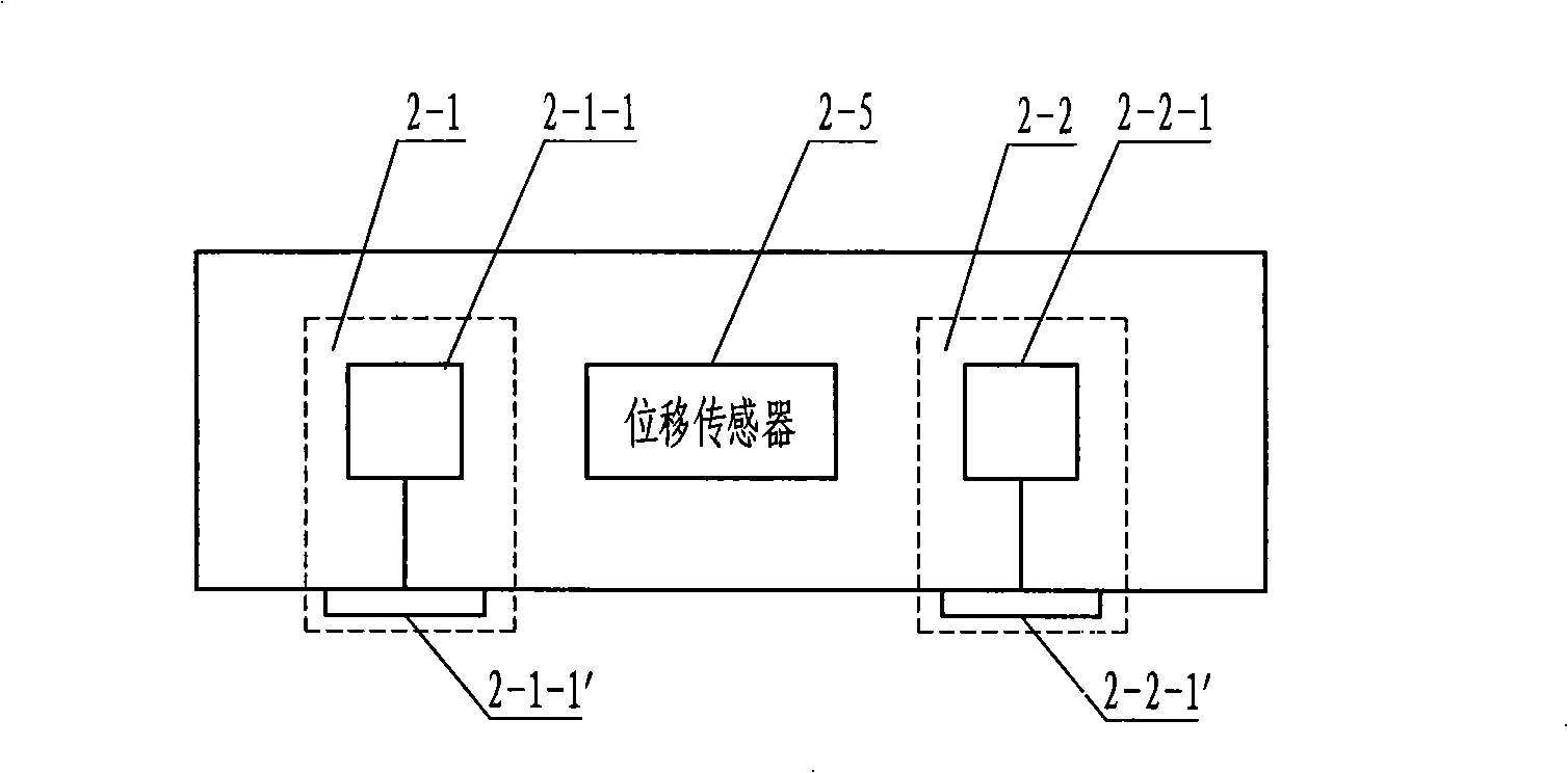
[0094] Specific implementation mode three: the following combination figure 2 , Figure 6 Describe this embodiment, the difference between this embodiment and Embodiment 1 is that the probe set 2 is composed of a transmitting terminal 2-1, a receiving terminal 2-2 and a displacement sensor 2-5, and the transmitting terminal 2-1 includes a transmitting piezoelectric chip 2-1-1, the first propagation medium 2-3 and the transmission angle changing device 2-1-1', the receiving terminal 2-2 includes the first receiving piezoelectric wafer 2-2-1, and the second propagation medium 2-4 And the first receiving variable angle device 2-2-1 ', the transmitting variable angle device 2-1-1' and the first receiving variable angle device 2-2-1' control the transmitting piezoelectric wafer 2-1-1 and the first The angle α between the receiving piezoelectric chip 2-2-1 facing the opposite surface and the workpiece 5 maintains the first critical refraction angle, and the first propagation mediu...
PUM
 Abstract
Description
Claims
Application Information
 - Generate Ideas
- Intellectual Property
- Life Sciences
- Materials
- Tech Scout
- Unparalleled Data Quality
- Higher Quality Content
- 60% Fewer Hallucinations
Browse by: Latest US Patents, China's latest patents, Technical Efficacy Thesaurus, Application Domain, Technology Topic, Popular Technical Reports.
© 2025 PatSnap. All rights reserved.Legal|Privacy policy|Modern Slavery Act Transparency Statement|Sitemap|About US| Contact US: help@patsnap.com


