
Fusion splicer for broken ends of hot melt wires

A fusion splicer and wire rod technology, applied in the field of additive manufacturing, can solve problems such as complex technology and equipment structure design, scrapped 3D printed parts, interruption of printing operations, etc., achieve broad market application prospects, good welding effect, and avoid waste Effect

Inactive Publication Date: 2018-01-16
于卫华
View PDF0 Cites 5 Cited by
  • Summary
  • Abstract
  • Description
  • Claims
  • Application Information

AI Technical Summary

Problems solved by technology

Since the middle and low-end printers do not have the function of automatically suspending the replacement of continuous wires, the printing operation must first estimate the length of the wires and the amount of consumables for 3D printing, which brings great inconvenience to the operation, and also causes a lot of waste of wire parts, which is even more serious. What’s more, if the wire length or the consumption of 3D printing consumables are not accurately estimated, the printing operation will be interrupted, and the 3D printing that needs to be printed at one time will be scrapped, causing unnecessary losses.
Although currently on the market, there have been technical solutions and equipment for 3D printing wire breakage welding through laser thermal fusion, electric heating thermal fusion pressing, etc., but the existing technology and equipment have complex structural design, high manufacturing cost, and difficult operation. Defects, can not solve the problem of 3D printing wire broken ends and welding at low cost, efficient and simple, and it is difficult to meet market demand

Method used


Image

  • Fusion splicer for broken ends of hot melt wires
  • Fusion splicer for broken ends of hot melt wires
  • Fusion splicer for broken ends of hot melt wires

Examples


Embodiment Construction

[0023] The present invention will be further described below in conjunction with accompanying drawing:

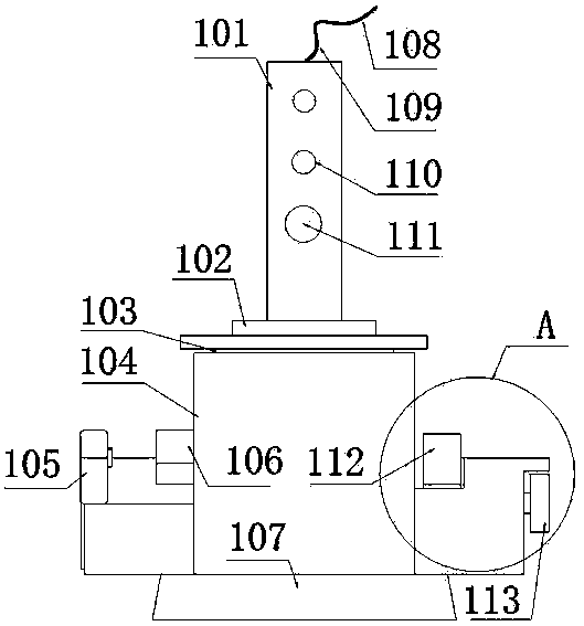
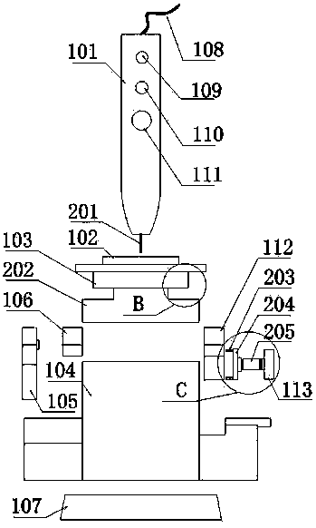
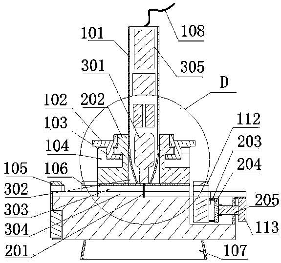
[0024] Such as figure 1 , figure 2 , image 3 , Figure 4 , Figure 5 , Figure 6 , Figure 7 , Figure 8 , Figure 9 , Figure 10 , Figure 11 , Figure 12 , Figure 13 As shown, a fusion splicer for thermally fusible wires according to the present invention includes a slot base, an upper slot member, and a heating device. 106. Movable latch 112, push hand wheel 113; the lower latch 304 is set at the setting position of the base 104, and merges with the upper latch 303 provided by the upper latch member to form a tubular shape; the fixed latch 106 is fixed At the setting position of the base 104, the flip cover is opened and closed by the spring piece a401 and the movable hasp a403. The upper and lower grooves are arranged in the flip cover to form a tubular shape, and the diameter is equal to the diameter of the lumen formed by the upper slot 303 and the lowe...


PUM


Abstract

The invention discloses a fusion splicer for broken ends of hot melt wires. The fusion splicer is used for fusing, lengthening and utilizing broken wires of the hot melt wires or remnant wires, and particularly brings great convenience to three-dimensional printers taking hot melt linear materials as raw materials. Three-dimensional printing wires are fused and lengthened without limitation in advance, so that the problem that automatic pause and replacement of splicing wires are not supported in the three-dimensional printing can be effectively solved, and waste of a large amount of remnant wires is avoided; more importantly, the condition that three-dimensional printing parts are scraped caused by feeding interruption of consumable materials is prevented. According to the fusion splicerdisclosed by the invention, hot melt butting, extrusion and sizing of broken end sections of to-be-fused wires are realized by a heating rod, a heating head and a movable clamping lock; the fusion splicer has the advantages of good welding effect, high strength, simplicity and convenience in operation and high efficiency; a clamping groove base, an upper clamping groove member and a heating deviceare arranged and are simple in structure, convenient to use, low in construction cost, economical and practical; clamping groove gaskets are additionally arranged on an upper clamping groove and a lower clamping groove, so that the fusion splicer is suitable for welding and lengthening operation of wires with different model numbers and specifications and has a broader market application prospect.

Description

technical field [0001] The invention relates to the field of additive manufacturing and other heat-meltable wire manufacturing equipment, in particular to a heat-fusible wire breaker fusion splicer. Background technique [0002] Additive manufacturing technology, commonly known as 3D printing, has a broad market prospect and is developing rapidly and popularizing rapidly. At present, FDM 3D printers using hot-melt linear materials as raw materials are widely used, and 3D printing wires are mostly produced by winding Online disks are sold, and wire fragments will continue to appear during use. Since the middle and low-end printers do not have the function of automatically suspending the replacement of continuous wires, the printing operation must first estimate the length of the wires and the consumption of 3D printing consumables, which brings great inconvenience to the operation, and also causes a lot of waste of wire parts, which is even more serious. More importantly, if...

Claims


Application Information

Patent Timeline
Patent Type & Authority Applications(China)
IPC IPC(8): B29C64/118B29C64/307B29C65/18B33Y40/00
Inventor 鲍硕鲍根华
Owner 于卫华
Learn More