
Inflation mould for filling

A technology of inflatable tires and inflatable nozzles is applied in the fields of formwork/template/work frame, building components, and on-site preparation of building components, which can solve problems such as large volume efficiency, complex production molds, and large transportation space.

Inactive Publication Date: 2008-12-10
邱则有
View PDF1 Cites 6 Cited by
  • Summary
  • Abstract
  • Description
  • Claims
  • Application Information

AI Technical Summary

Problems solved by technology

The production mold of this kind of thin-walled tube is complicated, it is inconvenient to carry, and because of its fixed shape and large volume, it takes up a lot of transportation space during transportation.

Method used


Image

  • Inflation mould for filling
  • Inflation mould for filling
  • Inflation mould for filling

Examples


Embodiment Construction

[0025] The present invention will be further described below in conjunction with the accompanying drawings and embodiments.

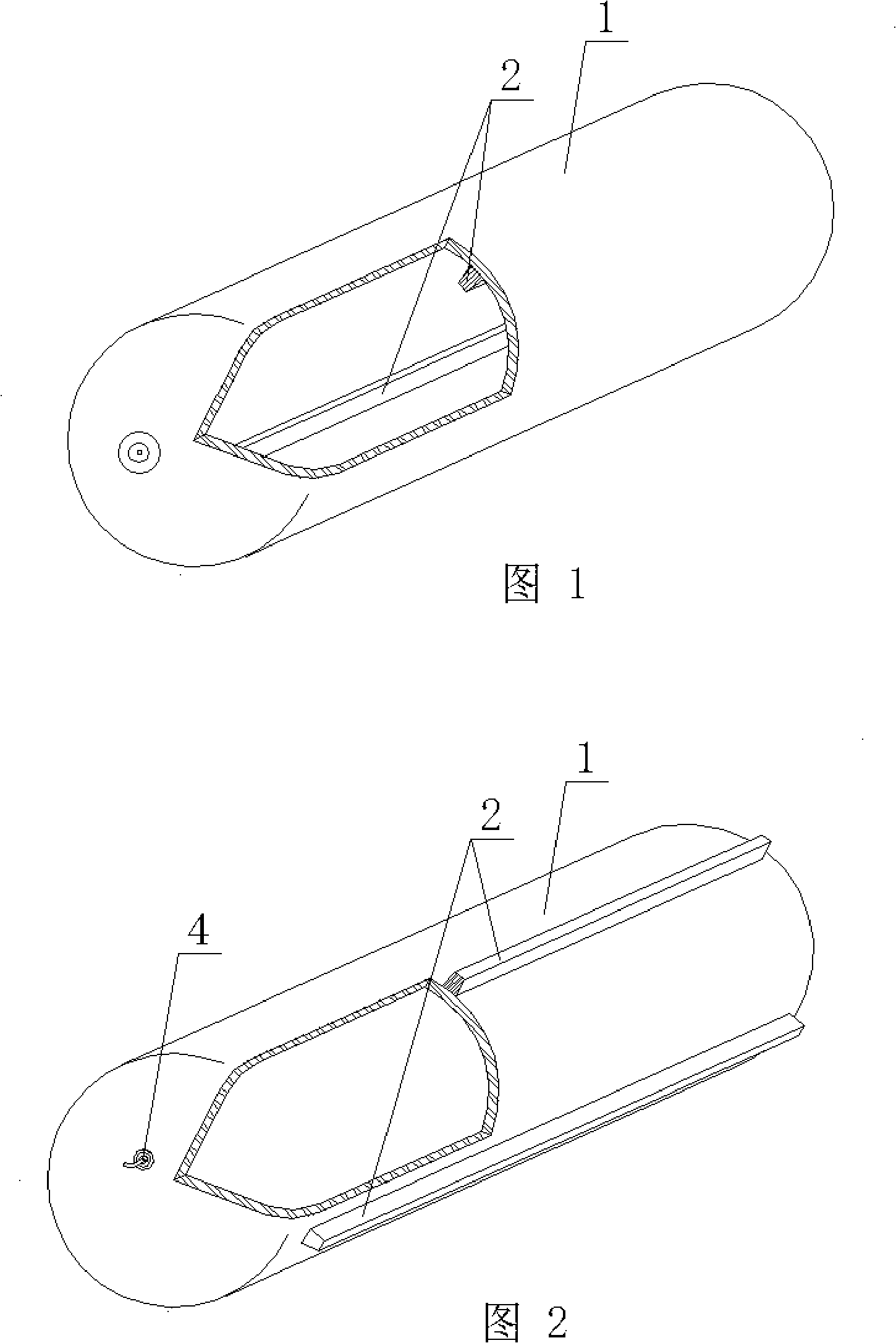
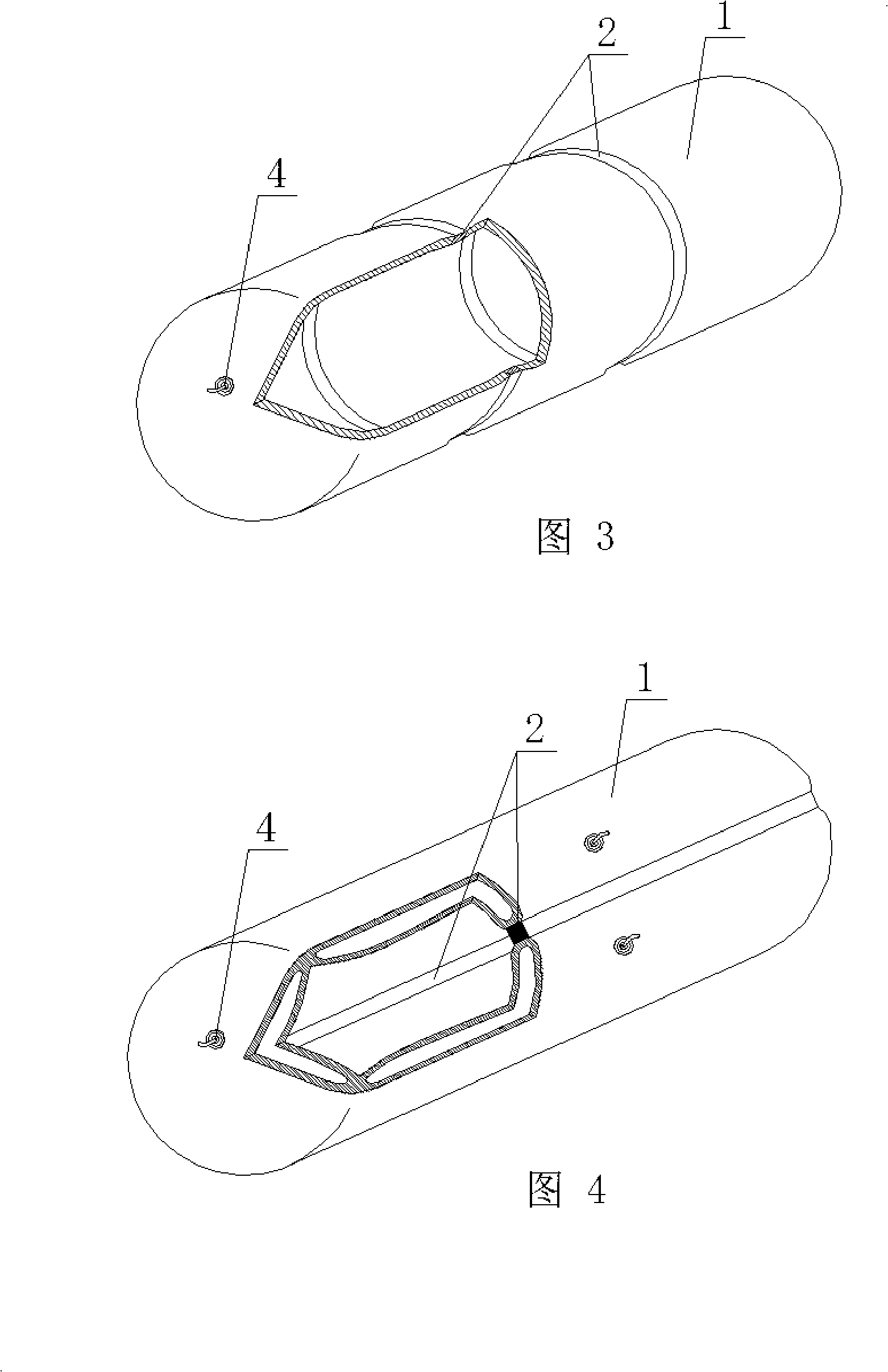
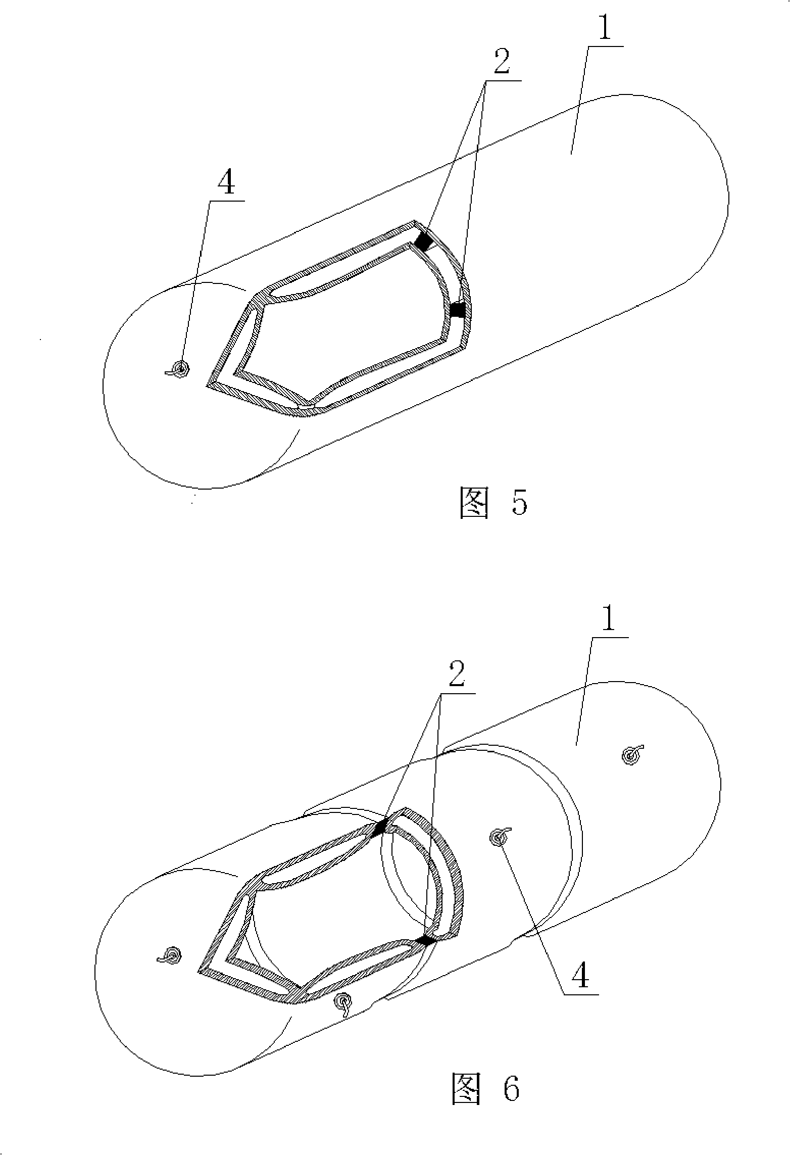
[0026] As shown in the drawings, the present invention includes an inflatable airbag membrane 1 and a skeleton 2, and is characterized in that the inflatable airbag membrane 1 is a tubular member, and the skeleton 2 is arranged on the membrane wall of the inflatable airbag membrane 1. Fig. 1 is a schematic structural diagram of Embodiment 1 of the present invention. In each accompanying drawing, 1 is an inflatable airbag membrane, and 2 is a skeleton. In each accompanying drawing, those with the same number have the same description. As shown in FIG. 1 , the inflatable airbag membrane 1 and the skeleton 2 are characterized in that the inflatable airbag membrane 1 is a tubular member, and the skeleton 2 is arranged on the membrane wall of the inflatable airbag membrane 1 .

[0027] The present invention is also characterized in that the skeleton 2 is di...


PUM


Abstract

An aerating moulding bed used for filling comprises an aerating air bag membrane (1) and a framework (2). The aerating moulding bed is characterized in that: the aerating air bag membrane (1) is a tubular member, and the framework (2) is arranged on the membrane wall of the aerating air bag membrane (1). Therefore, the aerating moulding bed is transported in an unaerated state and then is aerated and mounted on a construction site, thereby realizing convenient transportation and substantially reducing transportation cost; moreover, the framework arranged on the aerating moulding bed reinforces the mechanical property and the integrity of a moulding bed member, and increases the overall strength of the moulding bed member; meanwhile, a filling member has the characteristics of light deadweight, low cost, excellent shock resistance, simple, convenient and quick production and convenient transportation, etc., thereby achieving the aim of the invention. The aerating moulding bed is suitable to be used in hollow floor, roof, base slab, wall body and open frame bridge made of castinplace reinforced concrete, and is particularly suitable to be used in hollow beamless floor made of the castinplace reinforced concrete.

Description

(1) Technical field [0001] The invention relates to a pneumatic tire mold for filling. (2) Background technology [0002] At present, in the existing technology, the hole-forming components of cast-in-place hollow slabs are permanent mandrels, such as paper tubes, plastic tubes, metal bellows, and lightweight materials for mandrels. Small floor weight. For example, the patent number applied by the applicant is ZL99249755.8, and the name is a utility model patent named "fiber-reinforced thin-walled cylinder for filling cast-in-place reinforced concrete". It includes a hollow pipe body and a plug. The end is closed to form a thin-walled tube with a closed cavity, and at least one of the hollow tube body and the plug contains reinforcements such as fibers. The production mold of this kind of thin-walled pipe is complicated, and it is inconvenient to carry, and because of its fixed shape and large volume, it takes up a large amount of transportation space during transportation...

Claims


Application Information

Patent Timeline
Patent Type & Authority Applications(China)
IPC IPC(8): E04C1/00E04B5/36E04G11/04
Inventor 邱则有
Owner 邱则有
Learn More