
Smog detecting method and apparatus

A detection device and a smoke detection technology, applied in the field of smoke detection, can solve the problems of high false alarm rate, expensive sensors, and insufficient detection effect in large-scale spaces

Active Publication Date: 2008-12-03
IND TECH RES INST
View PDF2 Cites 12 Cited by
  • Summary
  • Abstract
  • Description
  • Claims
  • Application Information

AI Technical Summary

Problems solved by technology

[0003] Generally, traditional smoke detection devices, such as photoelectric smoke detectors, air sampling smoke detectors, etc., use the physical characteristics derived from the increase of smoke particles as the basis for fire judgment. Among them, the photoelectric smoke detector uses the emitted light source, If there are smoke particles in the air, they will scatter the light and cause the light to change, thereby detecting the occurrence of a fire. However, due to the limitation of the emission of the light source, the smoke detector set up in this way must have a limited detection range. , the detection effect for a large-scale space is bound to be insufficient; another type of air sampling smoke detector is to use the air distributed in the detection space to sample, and then analyze the sampled air composition to determine the occurrence of a fire , the sensor used in this kind of air sampling smoke detector itself is relatively expensive, and in order to sample air, it must be connected through pipes to facilitate detection
[0004] Therefore, the use of traditional sensors to detect smoke has the following disadvantages: 1. For spaces with high floors and large areas, such as factories, gymnasiums, shopping centers, etc., it is not easy to detect smoke and miss the golden period of early rescue; 2. It is impossible to accurately judge whether the smoke is related to the fire, resulting in misjudgment, resulting in a high false alarm rate (false alarms); 3. It is necessary to install a large number of smoke detectors, pipelines and central control systems, thus increasing the cost of the building
However, the above-mentioned patent document does not mention the accuracy of its detection method and device, nor does it apply other condition parameters and analysis techniques, such as chromaticity change analysis

Method used


Image

  • Smog detecting method and apparatus
  • Smog detecting method and apparatus
  • Smog detecting method and apparatus

Examples


Embodiment Construction

[0044] The present invention will be fully understood from the description of the following examples, so that those skilled in the art can complete it accordingly. However, the implementation of the present invention is not limited by the following examples.

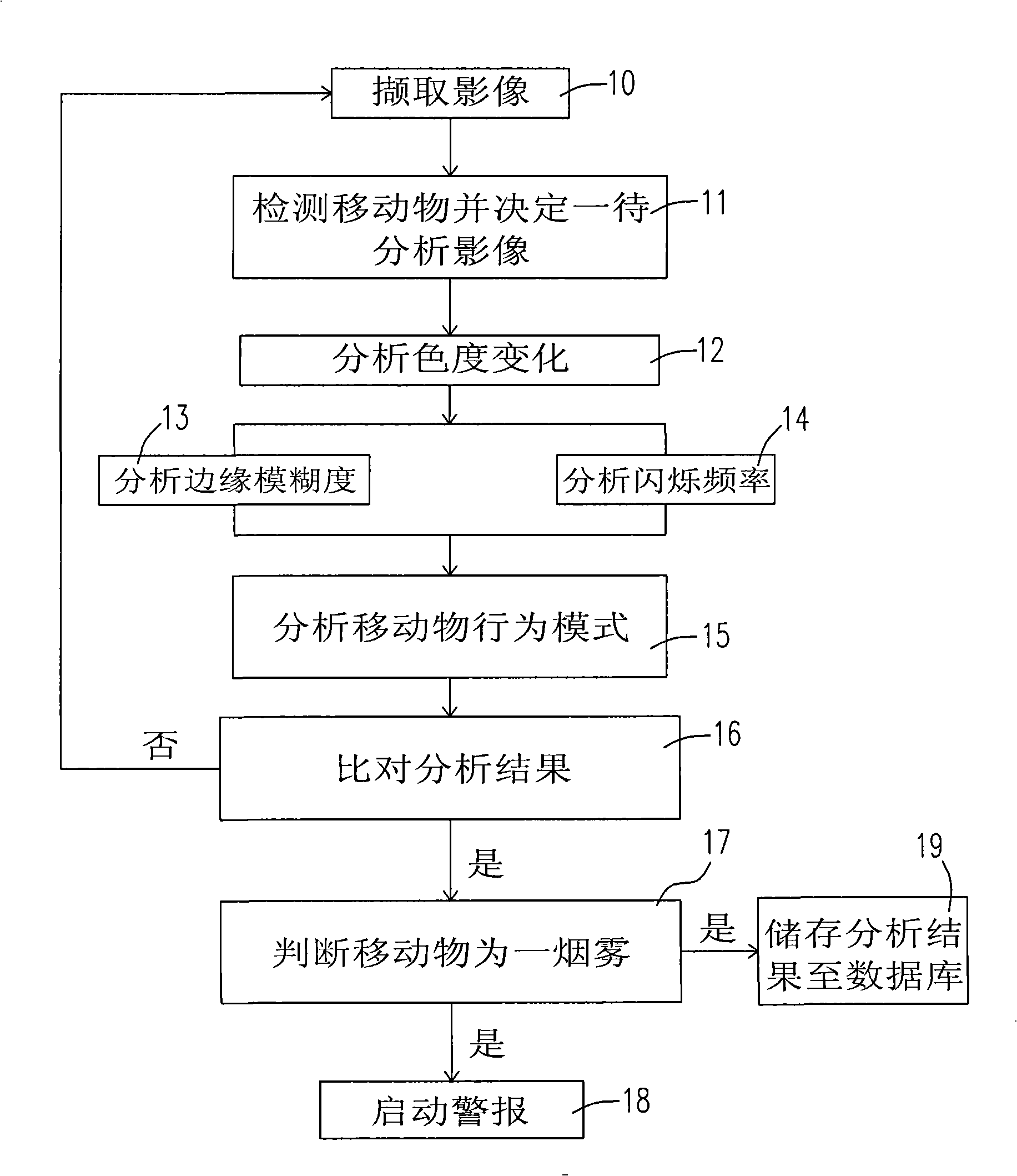
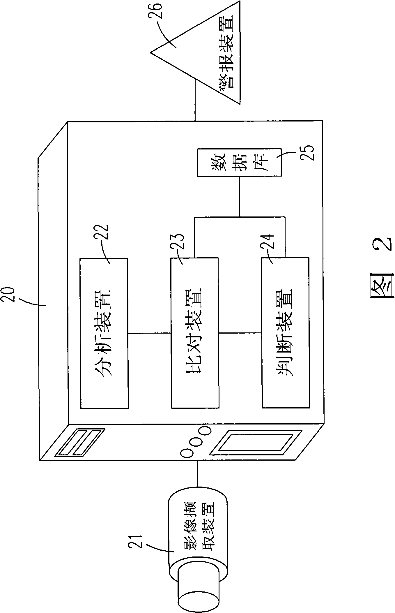
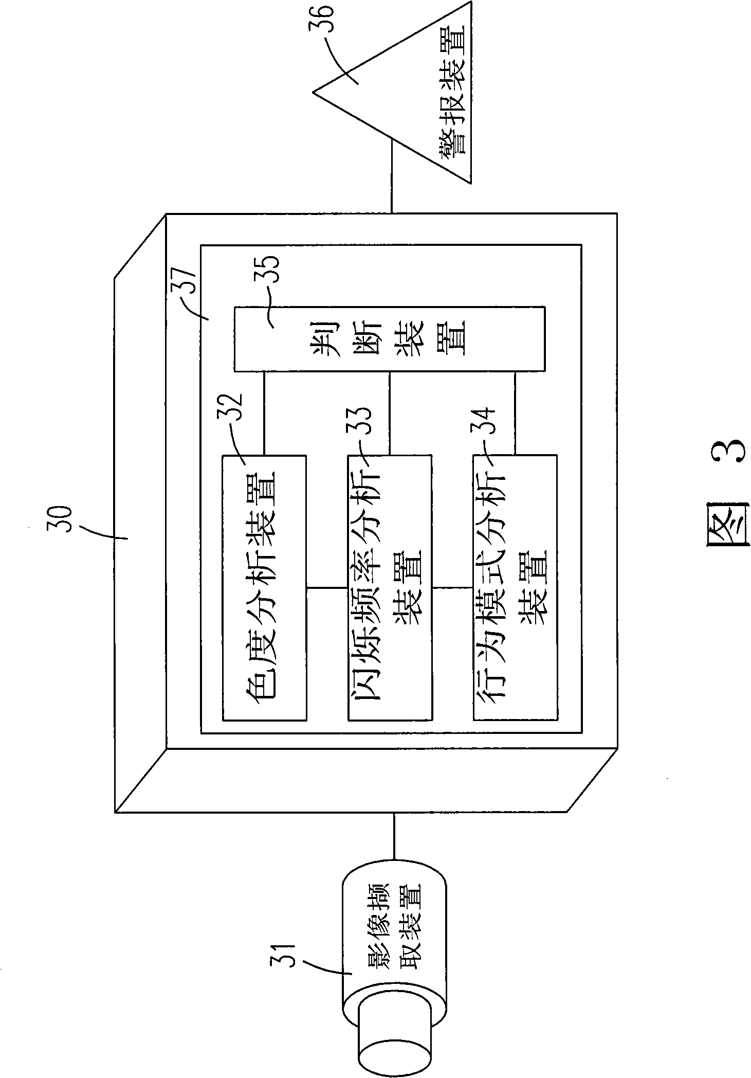
[0045]In order to overcome the problem of misjudgment in the current fire detection, which delays the timing of disaster relief, or often generates false alarms, the present application proposes a novel and progressive smoke detection method and device. In the detection method and device, the "feature determination" of an image with smoke (for example, whether it is fire smoke or not) is performed by various analysis or detection devices on the captured image to be analyzed with moving objects. Data detection and analysis are performed to obtain characteristic data of the image to be analyzed. In addition, the above-mentioned image feature data obtained by the smoke detection method and device of the present application ...


PUM


Abstract

The invention provides a method and a device for detecting smog. The method comprises the following steps: a plurality of images are captured, if a moving object appears in at least one image, the image with the moving object therein is determined to be the image to be analyzed; a chroma change of the image to be analyzed is analyzed, and at least one of an edge ambiguity and a flicker frequency of the image to be analyzed is analyzed; at least one analysis result of the steps and a preset characteristic are compared, if at least one analysis result accords with the preset characteristic, the moving objected is judged to be smog.

Description

technical field [0001] The present invention relates to a method and device for detecting smoke, and more particularly, to a method and device for detecting smoke using image analysis. Background technique [0002] In many fires, smoke occurs first, and even in some fire situations, such as smoldering, the combustion of substances only produces smoke but not flames. Therefore, smoke detection can be said to be one of fire prevention and fire rescue. A very important topic, the use of smoke detection systems can notify the fire when it first occurs, and carry out early fire fighting actions to greatly reduce the loss of life and property. [0003] Generally, traditional smoke detection devices, such as photoelectric smoke detectors, air sampling smoke detectors, etc., use the physical characteristics derived from the increase of smoke particles as the basis for fire judgment. If there are smoke particles in the air, it will scatter the light and cause the change of brightnes...

Claims


Application Information

Patent Timeline
Patent Type & Authority Applications(China)
IPC IPC(8): G01N21/25G01N15/00G08B17/10G06K9/00G06K9/46
Inventor 张升崑陆忠宪赵浩廷张世华许又仁黄坤霖王政暐
Owner IND TECH RES INST
Learn More