Control device for yarn trapper in sewing machine

A technology of a control device and a thread gripper, which is applied to the sewing machine control device, sewing equipment, sewing machine components, etc., can solve the problems of low accuracy, unsightly stitches, inconvenient use process, etc., and achieves high working stability. Effect

Inactive Publication Date: 2008-12-03
ZHEJIANG ZOJE SEWING MACHINE
View PDF0 Cites 7 Cited by
  • Summary
  • Abstract
  • Description
  • Claims
  • Application Information

AI Technical Summary

Problems solved by technology

[0004] Usually when the sewing machine is working, different thread tension conditions are required for different sewing materials, while the previous thread tensioners use manual adjustment of the thread tension disc of the thread tensioner to control the thread tension, which will cause inaccuracy High, resulting in unsightly stitches
[0005] Moreover, adjusting the tension of the spring is completely manual operation, which is done according to the operator's experience in the actual use process, which is very inconvenient in the specific use process

Method used


Image

  • Control device for yarn trapper in sewing machine
  • Control device for yarn trapper in sewing machine
  • Control device for yarn trapper in sewing machine

Examples


Embodiment Construction

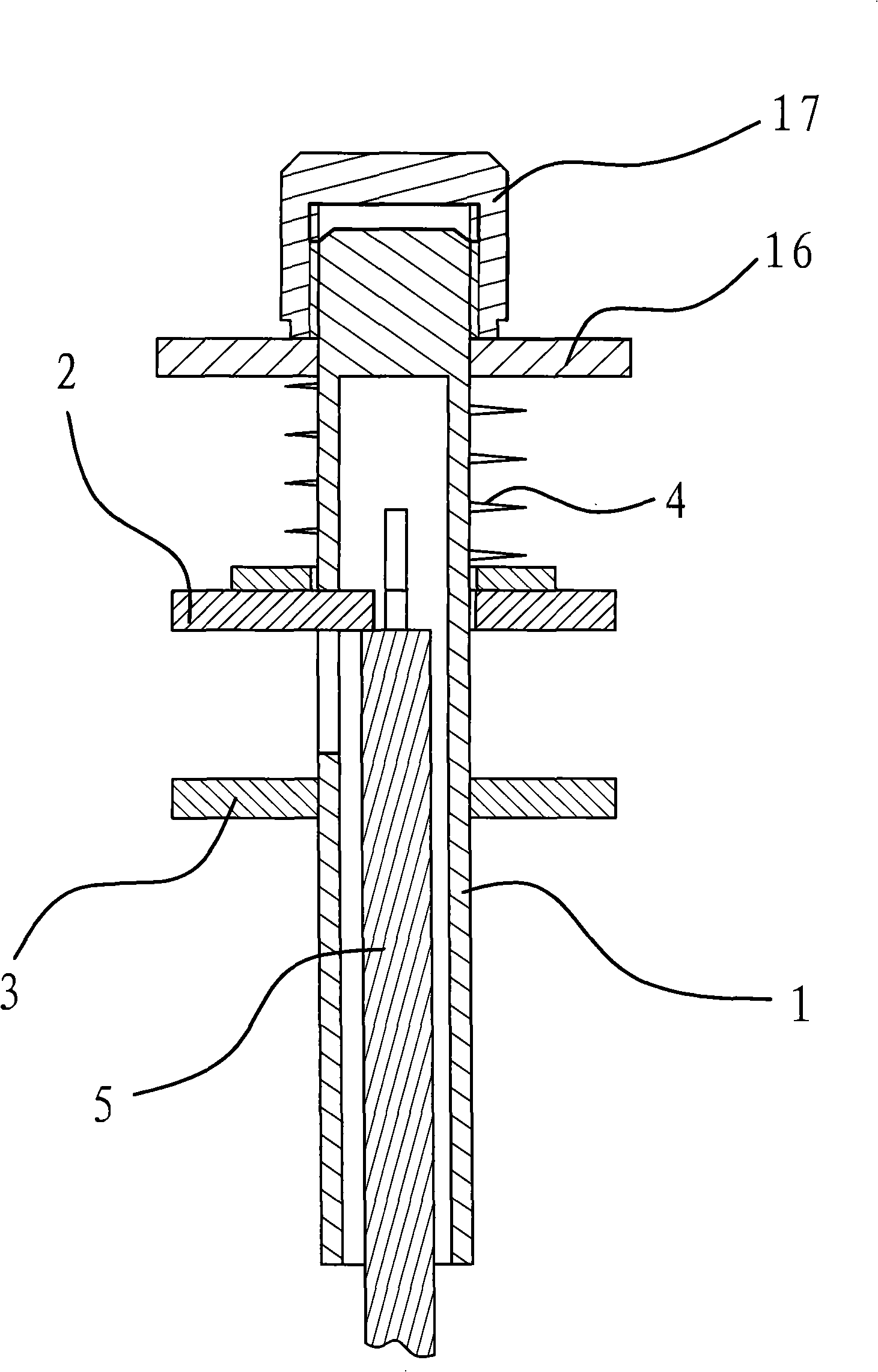
[0025] Such as figure 1 As shown, there is a thread clamp for clamping the suture in the sewing machine, and the tension of the sewing thread during the sewing process of the sewing machine can be adjusted by the thread clamp.

[0026] Thread tensioner is made up of parts such as bar body 1, upper chuck 2, lower chuck 3, spring 4 and thimble 5. The rod body 1 is cylindrical, and the lower chuck 2 is fixedly connected to the rod body 1 . The upper chuck 2 is sleeved on the rod body 1, and a spring 4 is also sleeved on the rod body 1. A clamping plate 16 is sleeved on the end of the rod body 1 and a nut 17 is threadedly connected. The above-mentioned spring 4 is in the upper clamp Between disc 2 and clamping plate 16. Under the elastic force of the spring 4 , the upper chuck 2 abuts against the lower chuck 3 , and the clamping plate 8 abuts against the nut 17 .

[0027] The thimble 5 is located in the rod body 1 , one end of the thimble 5 is connected with the above-mentioned...


PUM


Abstract

The invention provides a control device of a conductor holder in a sewing machine, belongs to the mechanical technology field, and solves the problems of the prior conductor holder, such as low accuracy, etc. caused by manually regulating a line tension pulley of the conductor holder for controlling the line tension. The control device of the conductor holder in the sewing machine is characterized in that the conductor holder is arranged on the frame side part of the sewing machine; the control device comprises an electric motor, an electromagnet, a wire loosing rod and a wire clamping block; the electric motor is permanently connected with the frame; a wire clamping transmission mechanism which enables the wire clamping block to compress a spring is arranged between the electric motor and the wire clamping block; the electromagnet is permanently connected with the frame; and a wire loosing transmission mechanism which enables the wire loosing rod to prop against the outer end of a thimble is arranged between the electromagnet and the wire loosing rod. The control device realizes line tightening by the electric motor and the line clamping transmission mechanism, and the clamping force between an upper chuck and a lower chuck is always maintained to be proper during the process of line tightening. The control device of the conductor holder in the sewing machine has higher working stability and simple structure.

Description

technical field [0001] The invention belongs to the technical field of machinery, and relates to a sewing machine, in particular to a control device for a thread clamp in the sewing machine. Background technique [0002] There is a thread gripper for clamping the suture in the sewing machine, by which the tension force of the suture in the sewing process of the sewing machine can be adjusted. The thread clamp includes a cylindrical rod body, an upper chuck, a lower chuck, and a spring sleeved on the rod body, and the upper chuck and the lower chuck abut against each other under the elastic force of the spring. A thimble is arranged in the rod body, the inner end of the thimble is pushed against the above-mentioned upper chuck, and the outer end of the thimble extends out of the rod body. [0003] The suture passes between the above-mentioned upper chuck and the lower chuck, the elastic tension of the spring is adjusted, and the clamping force between the upper chuck and the...

Claims


Application Information

Patent Timeline
Patent Type & Authority Applications(China)
IPC IPC(8): D05B47/04D05B69/00
Inventor 佐藤秀一严海军王林陈栩华
Owner ZHEJIANG ZOJE SEWING MACHINE
Why Eureka
Try Eureka