
Double-cycling anaerobic reactor

An anaerobic reactor and double-cycle technology, applied in anaerobic digestion treatment, waste fuel, etc., can solve the problems of complex water distribution system, high energy, and high suspended solids, so as to ensure degradation efficiency, reduce power consumption, and save energy. The effect of circulating energy

Inactive Publication Date: 2010-04-14
永兴县皓天环保科技发展有限责任公司
View PDF6 Cites 0 Cited by
  • Summary
  • Abstract
  • Description
  • Claims
  • Application Information

AI Technical Summary

Problems solved by technology

The circulation mode of the sewage in the reactor is basically a single circulation mode. When the IC reactor is in the initial stage of equipment start-up and low-concentration organic wastewater enters, it is difficult to fully contact with the bacteria and anaerobic sludge used for treatment. The start-up time of biochemical treatment Long, it is difficult to operate normally under low load conditions, the reactor EGSB has a large cycle power, and more suspended matter is brought out; the water distribution system of the UASB reactor is complicated, and short-flow phenomenon is prone to occur
However, the degradation efficiency of COD in wastewater is low; the single-cycle method is used to ensure basically the same treatment effect, and the height of the reactor is correspondingly required to be higher, so that the energy for transporting treated water is more, and the energy-saving effect is not good.

Method used


Image

  • Double-cycling anaerobic reactor
  • Double-cycling anaerobic reactor

Examples


Embodiment Construction

[0013] The technology of the present invention will be further described below in conjunction with the accompanying drawings and embodiments.

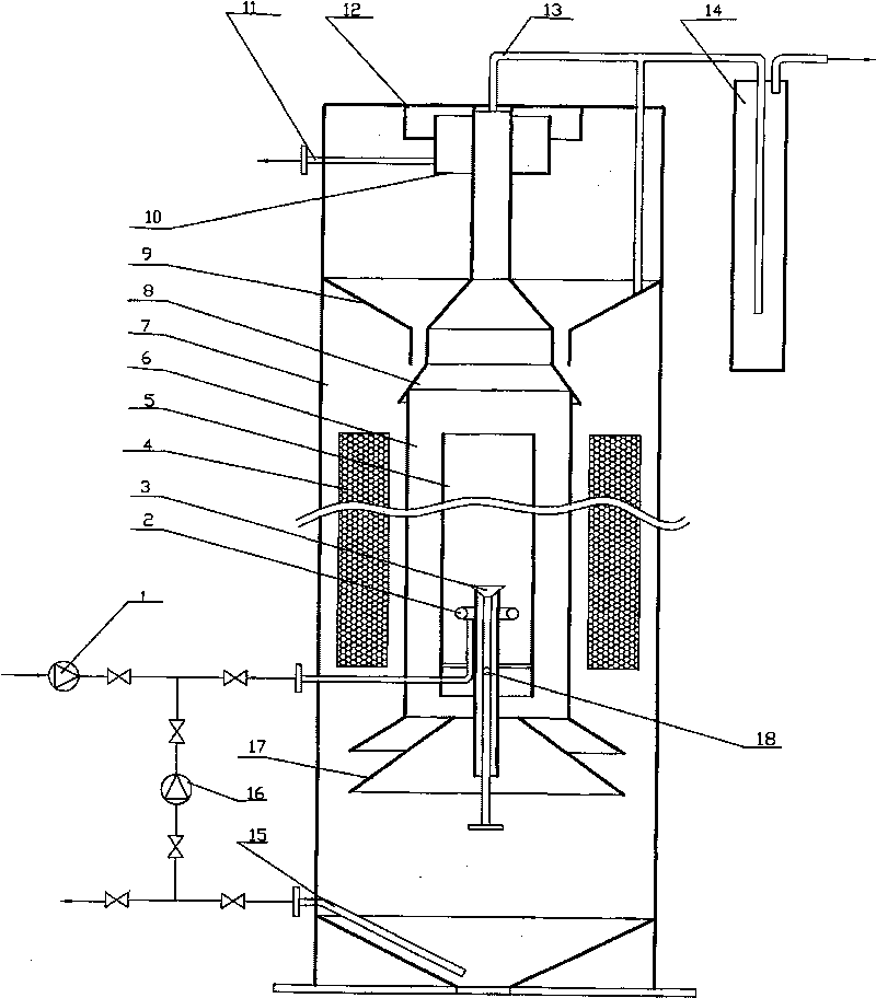
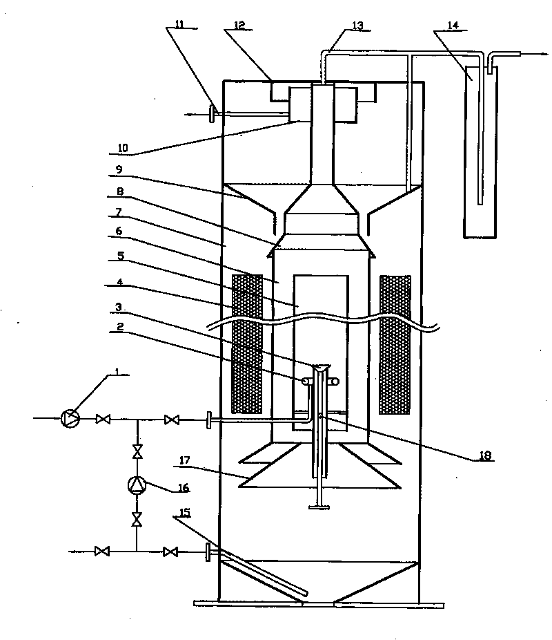
[0014] The double-cycle anaerobic reactor as shown in the figure includes a reactor housing 7, a sewage lifting pump 1 arranged outside the housing, a backflow circulation pump 16, a pipeline valve and an outlet pipe 11 for connection, and a backflow circulation pump 16 The connected mud discharge return pipe 15 and the elastic packing 4 arranged in the shell are characterized in that: the center of the reactor shell 7 is provided with a concentric or symmetrical baffle ascending guide cylinder 5 and a descending liquid guide cylinder 6 sequentially from the inside to the outside and filler 7; the bottom of the liquid-rising guide tube 5 is provided with a water inlet distribution pipe 2 connected to the sewage lifting pump 1 and a biogas lifting reflux device 3; The upper part of the downcomer guide tube 6 is provided with a central a...


PUM


Abstract

The invention discloses a bicirculating anaerobic reactor, which comprises a shell, a lifting pump, a circulating pump, a hydraulic control water seal, and a pipeline value used for connection, wherein, the center of the shell, from inside to outside, is orderly provided with a liquid ascending guide sleeve, a liquid descending guide sleeve and an elastic filler which are concentric or symmetrically deflective; the lower part of the liquid ascending guide sleeve is provided with a water inlet distribution pipe and a methane lifting reflux device which are connected with a sewage lifting pump;the bottom of the liquid descending guide sleeve is provided with a bottom gas ascending cover, the upper part of the liquid descending guide sleeve is provided with a central gas skirt, and an edge gas skirt is arranged at the periphery of the central gas skirt; and the upper part of the central gas skirt, from the bottom up, is orderly provided with an overflow trough and a scum baffle, a wateroutlet pipe is connected to the overflow trough, and the bottom of the reactor is provided with a sludge collection and reflux space. The reactor adopts an external small flow reflux and internal methane lifting reflux technology, can fully contact strains and anaerobic sludge which are used for treatment at a start initial stage and during the entrance of low-concentration organic wastewater, hasshorter starting time of biochemical treatment, can normally operate under the condition of low load, can also ensure that the degradation efficiency of COD in wastewater under the low load and highloadis high, and save the energy.

Description

technical field [0001] The invention belongs to sewage treatment equipment, in particular to a double-cycle anaerobic reactor. Background technique [0002] As the main equipment of sewage treatment, anaerobic reactor plays a very important role in the process of sewage treatment. There are three commonly used anaerobic reactors: UASB, EGSB and IC reactor. The circulation mode of the sewage in the reactor is basically a single circulation mode. When the IC reactor is in the initial stage of equipment start-up and low-concentration organic wastewater enters, it is difficult to fully contact with the bacteria and anaerobic sludge used for treatment. The start-up time of biochemical treatment Long, it is difficult to operate normally under low load conditions, the reactor EGSB has a large cycle power, and more suspended matter is brought out; the water distribution system of the UASB reactor is complicated, and short-flow phenomenon is prone to occur. However, the degradation ...

Claims


Application Information

Patent Timeline
Patent Type & Authority Patents(China)
IPC IPC(8): C02F3/28
CPCY02E50/30
Inventor 陈皓鋆陈曙平
Owner 永兴县皓天环保科技发展有限责任公司
Learn More