Oscillatory circuit of tunable filter with minimize phase noise

A technology of oscillation circuit and filter, which is applied to multiple resonant circuits tuned to different frequencies, circuits, power oscillators, etc., which can solve the problems of high phase noise, sensitivity to temperature and process changes, and sensitivity to process changes, etc.

Inactive Publication Date: 2008-11-12
OPTIS CELLULAR TECH LLC
View PDF0 Cites 8 Cited by
  • Summary
  • Abstract
  • Description
  • Claims
  • Application Information

AI Technical Summary

Problems solved by technology

Third, the finite impedance of the current source at RF frequencies increases the resonator loading, which also makes the phase noise unnecessarily high
However, such a configuration would still have drawbacks. First, the current bias is very sensitive to gate / base bias (bias) variations, and thus to temperature and process variations, similar to the configuration of Figure 1B
In addition, it only provides optimized performance in a very narrow frequency band, and performs poorly in frequency tuning, and is also very sensitive to process variations
This problem can be severe, especially at low offset frequencies

Method used


Image

  • Oscillatory circuit of tunable filter with minimize phase noise
  • Oscillatory circuit of tunable filter with minimize phase noise
  • Oscillatory circuit of tunable filter with minimize phase noise

Examples


Embodiment Construction

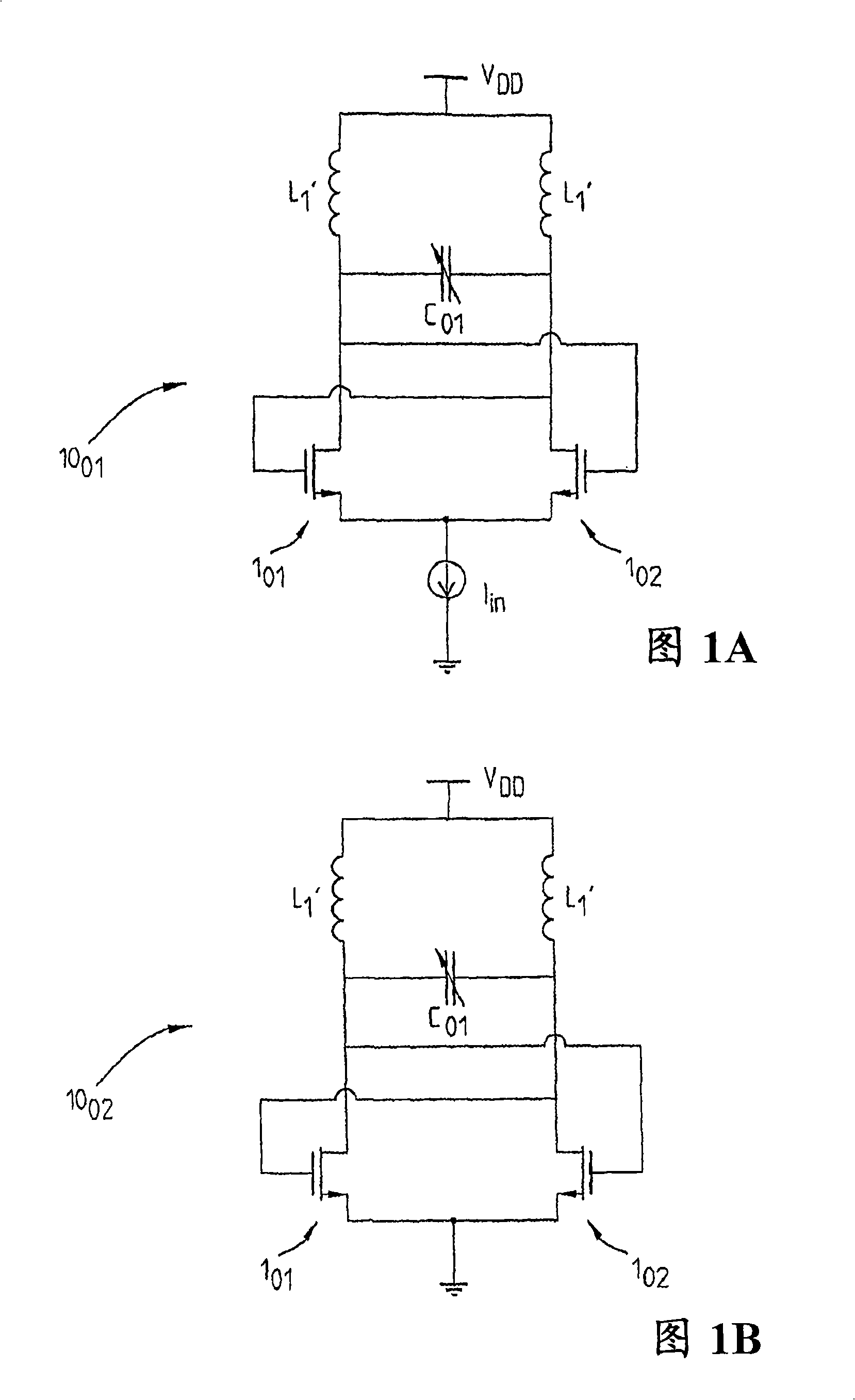
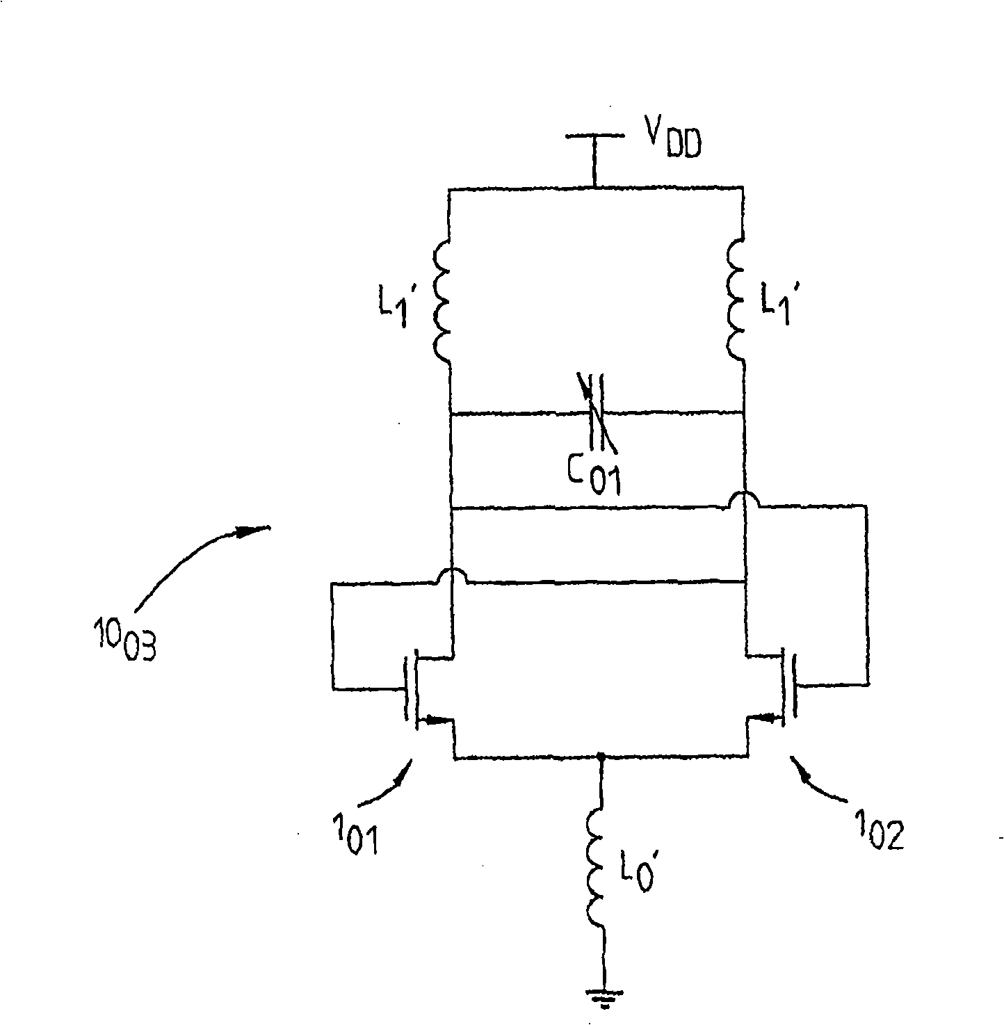
[0037] Figures 1A-1C illustrate the prior art and the disadvantages associated therewith have been discussed in the background section above, which constitute DD , and includes first and second switching transistors 1 01 ,1 02 And varactor diode (varactor) C 01 A cross-coupled differential pair VCO of 10 01 、10 02 、10 03 standard configuration. Varactor diode C 01 For example, it can be implemented as a MOS capacitor, or as a p-n junction, etc. Therefore, as described in the Background section, the current source I in is used to set the current bias in the Figure 1A implementation, while Figure 1B only shows ground changes, and Figure 1C shows that the power flow has been replaced by an inductor L 01 installation.

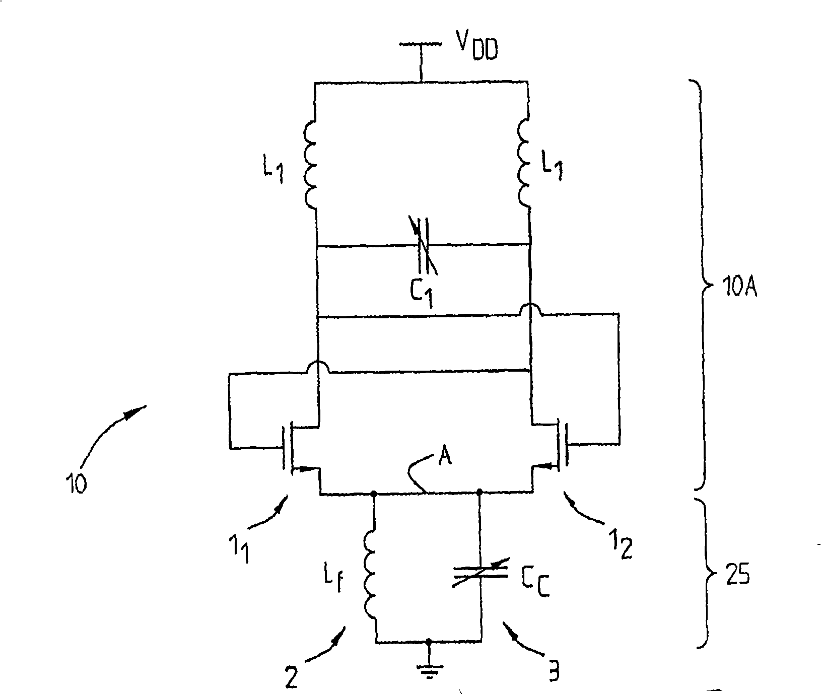
[0038] figure 2 A first embodiment of the present invention is shown. The oscillating circuit arrangement 10 here comprises a cross-coupled differential pair VCO structure in a conventional manner. First (functional) switching transistor 1 1 and the ...


PUM


Abstract

The present invention relates to an oscillating circuit arrangement (10) comprising a resonating arrangement with a first resonance frequency (coo) comprising a voltage controlled oscillator arrangement (10A). It further comprises a tunable filter arrangement (25) connected to the source node of said voltage controlled oscillator (VCO) arrangement (10A). The filter arrangement (25) particularly comprises an equivalent current source resonating at a second resonance frequency c omiga f, the second resonance frequency being a multiple n, n= 1 or 2 of the first resonance frequency (alpha>0), n being equal to the minimum number of switch transistors (1, 2) required for oscillation of the VCO arrangement. The filter arrangement particularly comprises an inductor (2) connected in parallel with a capacitor (3), the capacitor (3) being adapted to be tunable such that the phase noise of the resonating arrangement (10A) can be minimized through tuning of the filter arrangement (25).

Description

technical field [0001] The invention relates to an oscillating circuit arrangement having resonant means resonating at a first resonance frequency and comprising a voltage controlled oscillator arrangement. The invention also relates to a method of minimizing the phase noise of an oscillating circuit arrangement comprising resonant means resonating at a first resonance frequency and comprising a voltage controlled oscillator arrangement. Background technique [0002] Many different oscillating circuit arrangements comprising one or more voltage controlled oscillators (designated VCO in the following) are known. Keeping phase noise as low as possible is critical. Commonly used VCO topologies include common-source / common-emitter cross-coupled differential pairs, which are attractive for their low phase noise, robust operation, and the fact that they can be made very small. In FIG. 1A , which shows the state of the art, a cross-coupled differential pair VCO is shown schematic...

Claims


Application Information

Patent Timeline
Patent Type & Authority Applications(China)
IPC IPC(8): H01J5/22H03B5/12H03J7/08
CPCH03J3/32H03B5/1228H03B5/1215H03B5/1284H03B5/124H03B5/1278
Inventor H·雅各布森L·阿斯佩米尔
Owner OPTIS CELLULAR TECH LLC
Why Eureka
Try Eureka