
Back light module and LCD device

A liquid crystal display and backlight module technology, applied in static indicators, optics, instruments, etc., can solve the problems of poor heat dissipation and poor display quality of the backlight module, and achieve the effect of good heat dissipation and high brightness display quality.

Inactive Publication Date: 2008-11-12
INNOLUX CORP
View PDF0 Cites 26 Cited by
  • Summary
  • Abstract
  • Description
  • Claims
  • Application Information

AI Technical Summary

Problems solved by technology

[0007] In view of this, the purpose of the present invention is to provide a backlight module to solve the heat dissipation and assembly problems of the backlight module
[0008] Another object of the present invention is to provide a liquid crystal display to solve the problem of poor display quality due to poor heat dissipation of the backlight module

Method used


Image

  • Back light module and LCD device
  • Back light module and LCD device
  • Back light module and LCD device

Examples


Embodiment Construction

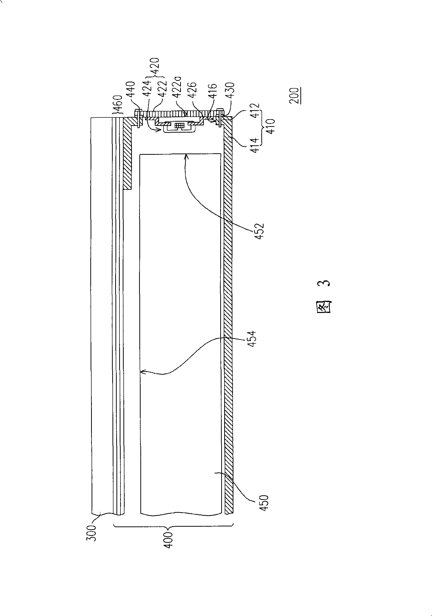
[0062] FIG. 3 is a schematic cross-sectional view of a liquid crystal display according to a first embodiment of the present invention. Referring to FIG. 3 , the liquid crystal display 200 includes a liquid crystal display panel 300 and a backlight module 400 , wherein the backlight module 400 is disposed under the liquid crystal display panel 300 to provide the surface light source required by the liquid crystal display panel 300 for displaying images. The backlight module 400 will be further described in detail below, so that those skilled in the art can clearly understand the present invention.

[0063] Figure 4 It is an exploded schematic view of the supporting frame and the LED module in the first embodiment of the present invention, and Figure 5 for Figure 4 The schematic diagram of the light-emitting diode module assembled in the support frame, Figure 6 is Figure 5 Front view of the support frame with the LED module along the Z direction. Please also refer to Figu...


PUM


Abstract

The invention discloses a backlight module which is applicable to a liquid crystal display (LCD). The backlight module of the invention comprises a support frame and a light emitting diode (LED) module, wherein, the support frame is provided with at least a through hole, and the LED module comprises at least a circuit board and a plurality of LEDs. The circuit board of the LED module is provided with a bearing surface and the LEDs of the LED module electrically connected with the circuit board are configured on the bearing surface of the circuit board, wherein, the LEDs run through the through hole and are positioned in the support frame; moreover, the circuit board is fixed outside the support frame by the bearing surface towards the support frame. As the circuit board is exposed outside the support frame, the heat energy generated by the LEDs can be rapidly transmitted outside the backlight module, thus leading the backlight module to having good heat dissipation efficiency.

Description

technical field [0001] The present invention relates to a light source module and a display, and in particular to a backlight module (backlight module) and a liquid crystal display (Liquid Crystal Display device, LCD device). Background technique [0002] With the progress of science and technology, displays are gradually widely used by the public. To meet people's needs, displays have changed from larger and heavier cathode ray tubes (Cathode Ray Tube, CRT) to thinner and lighter liquid crystal displays (Liquid Crystal Display, LCD) as the mainstream. A liquid crystal display is composed of a liquid crystal display panel and a backlight module. Since the liquid crystal display panel itself does not emit light, the backlight module must be used as a light source to provide light so that the liquid crystal display panel can display images. Due to the characteristics of high brightness and small size, light emitting diodes have been gradually used in backlight modules, so th...

Claims


Application Information

Patent Timeline
Patent Type & Authority Applications(China)
IPC IPC(8): G02F1/13357G02F1/133H05K1/18G02F1/1335
Inventor 谢鸿生王子昌
Owner INNOLUX CORP
Learn More