Chemical conversion film formation-evaluating liquid for steel
A chemical conversion film and steel technology, applied in the direction of using chemical indicators for analysis, scientific instruments, optical testing flaws/defects, etc., can solve the problems that do not mention the mixing ratio of iron reagent solution and phenolphthalein solution, and achieve the evaluation of uniformity Effect
- Summary
- Abstract
- Description
- Claims
- Application Information
AI Technical Summary
Problems solved by technology
Method used
Image

Examples
Embodiment 1
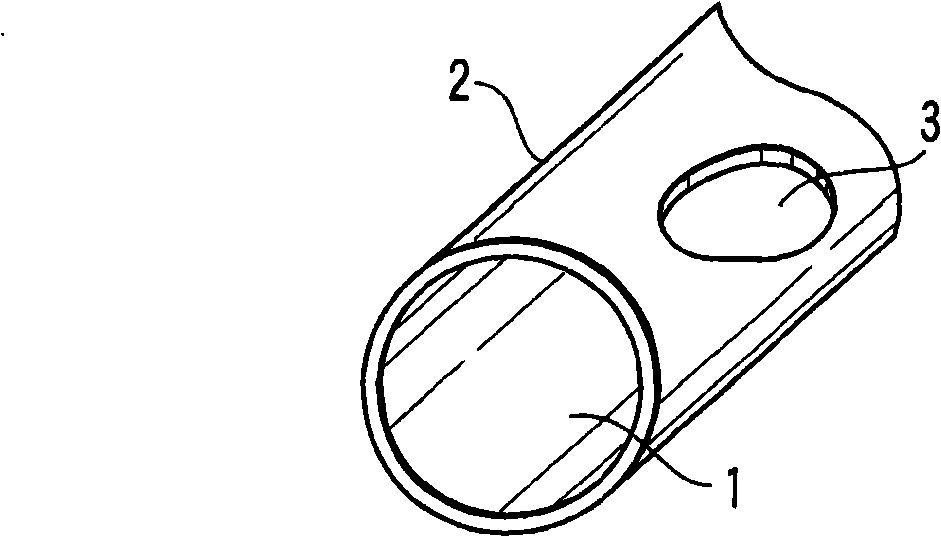
[0030] figure 1 It shows the case where the defect part of the chemical conversion coating was intentionally formed by masking after shot peening. Such as figure 1 As shown, the zinc phosphate chemical conversion coating 2 is formed on almost the entire surface of the steel material 1 through zinc phosphate treatment. In addition, the thin oxide film 3 formed after shot peening remains by masking a part of the steel material 1 .
[0031] Here, the steel wire section shown in the illustration is only a schematic diagram showing the chemical conversion coating and the structure of the steel material, but actually the end surface of the steel wire is also covered with the chemical conversion coating. When this steel coil spring was immersed in the evaluation solution and then dried, no color development was confirmed on most surfaces. However, a part of the surface was colored blue, and the part that had not been chemically converted was colored pink by masking. The blue colo...
Embodiment 2
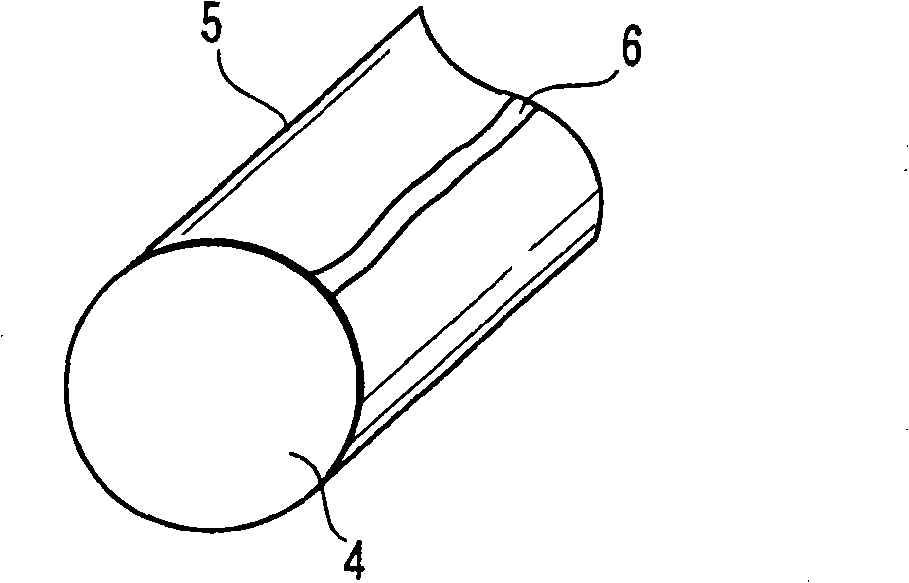
[0035] figure 2 The case where there is no chemical conversion coating on the surface of the steel material 4 and the whole surface is shot-peened as shown is shown. At this time, a thin oxide film 5 is directly formed on the surface of the steel material 4 . Here, the cross-section of the steel wire shown in the figure only shows the structure of the oxide film and the steel material, but actually the end surface of the steel wire is also covered with the oxide film. At this time, for example, if figure 2 As shown, impressions 6 are partially produced during winding. At this time, the residual deformation in this part is relatively large, and it is in a state where iron is easily precipitated compared with other parts.
[0036] When the coil spring having the above structure was dipped in the evaluation solution and then dried, mainly the portion where the imprint 6 was present was colored blue, and most of the portions other than the portion where the imprint 6 was pres...
Embodiment 3
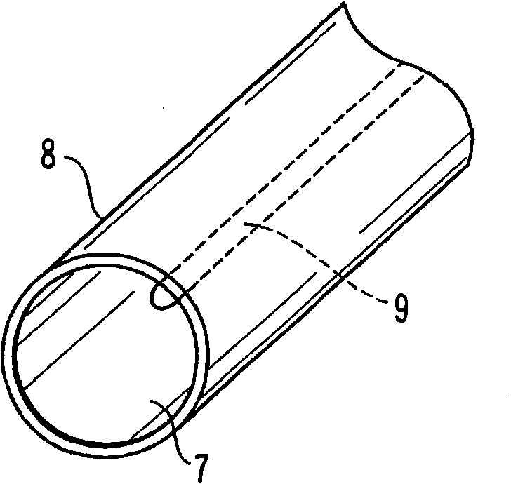
[0039] image 3 It shows the case where the surface of the steel material 7 is subjected to the zinc phosphate chemical conversion treatment, and the zinc phosphate chemical conversion film 8 is formed on the entire surface. A part of the steel material 7 has an imprint 9 when the coil spring was wound, and thus is in a state of large residual deformation. Here, the steel wire section shown in the illustration is only a schematic diagram of the structure of the chemical conversion coating and the steel material, but actually the steel wire section is also covered with the chemical conversion coating.
[0040] The coil spring having the above configuration was immersed in the evaluation liquid and dried, and a very small part of the coiled spring was dispersed and developed a blue color. The reason for this is considered to be the result that the iron composition of the chemical conversion coating is not uniform or the residual deformation is not uniform, although it is a slig...
PUM
| Property | Measurement | Unit |
|---|---|---|
| height | aaaaa | aaaaa |
Abstract
Description
Claims
Application Information
 - R&D
- Intellectual Property
- Life Sciences
- Materials
- Tech Scout
- Unparalleled Data Quality
- Higher Quality Content
- 60% Fewer Hallucinations
Browse by: Latest US Patents, China's latest patents, Technical Efficacy Thesaurus, Application Domain, Technology Topic, Popular Technical Reports.
© 2025 PatSnap. All rights reserved.Legal|Privacy policy|Modern Slavery Act Transparency Statement|Sitemap|About US| Contact US: help@patsnap.com