
Erecting machine of bridge span for road and railway

A bridge erecting machine, highway and railway technology, which is used in the erection/assembly of bridges, bridges, bridge construction, etc. The requirements that must be guaranteed, to achieve the effect of shortening the transfer time, simple assembly, and large workload

Active Publication Date: 2008-10-29
HANDAN CHINA RAILWAY BRIDGE MACHINERY
View PDF1 Cites 8 Cited by
  • Summary
  • Abstract
  • Description
  • Claims
  • Application Information

AI Technical Summary

Problems solved by technology

[0002] The domestic walking type telescopic arm type single guide beam bridge erecting machine (patent number: 01224076.1) is a utility model patent applied by the applicant in 2001. In the above prior art, there is a height difference between the highest position and the lowest position of the bridge erecting machine It cannot effectively guarantee ≥3000mm, and cannot meet the requirements of the construction site limit for the minimum height of the bridge erecting machine and the space of the bridge erecting frame girder. Problems such as the failure of No. 3 pillar to support

Method used


Image

  • Erecting machine of bridge span for road and railway
  • Erecting machine of bridge span for road and railway
  • Erecting machine of bridge span for road and railway

Examples


Embodiment Construction

[0038] The embodiments of the present invention are further described below in conjunction with the accompanying drawings, but they are not intended to limit the present invention.

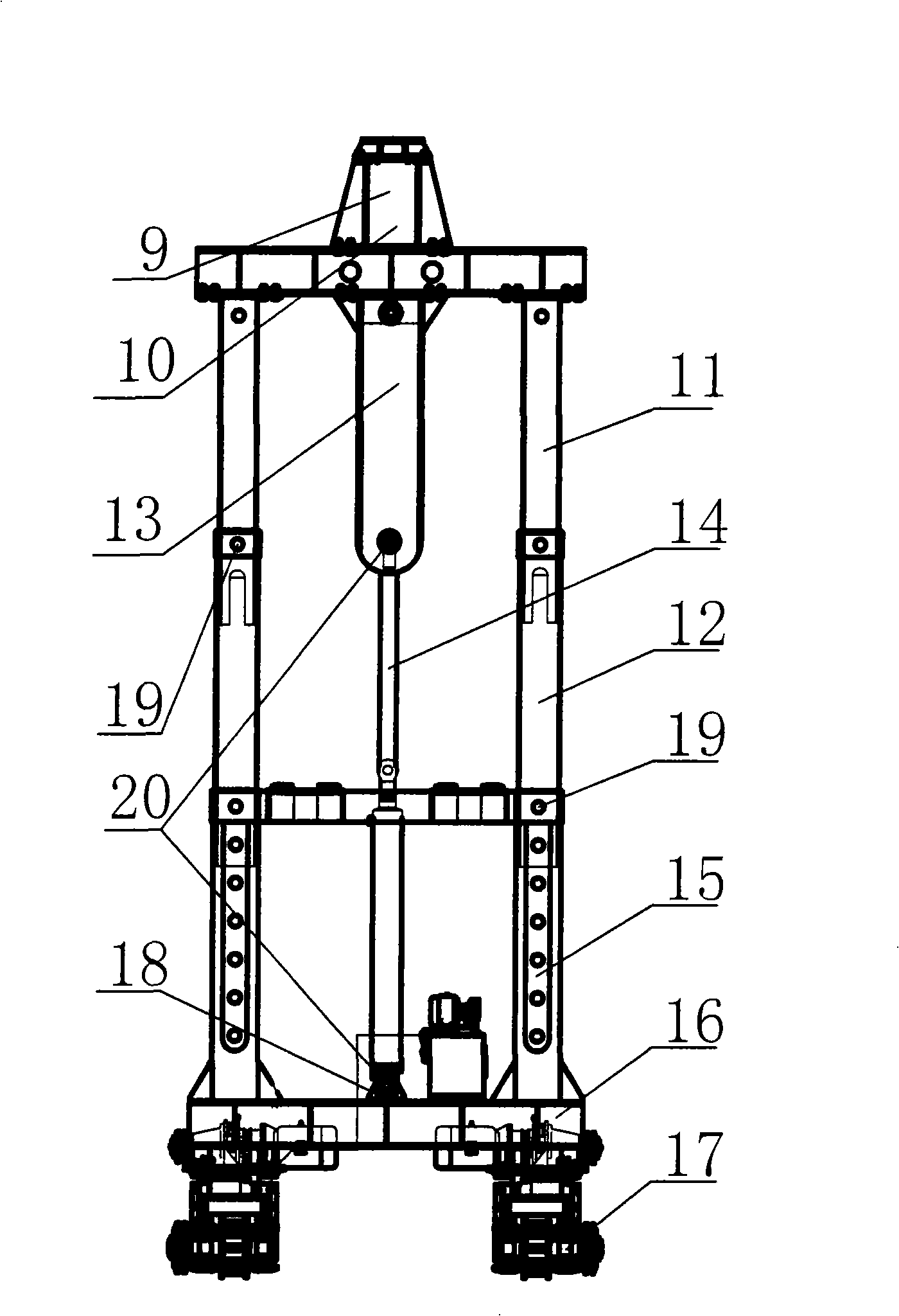
[0039] The overall structure of this embodiment is as shown in the figure, which includes booms I and II, crane beam trolleys on the boom, pillars, and hydraulic traverse mechanism; it also includes:

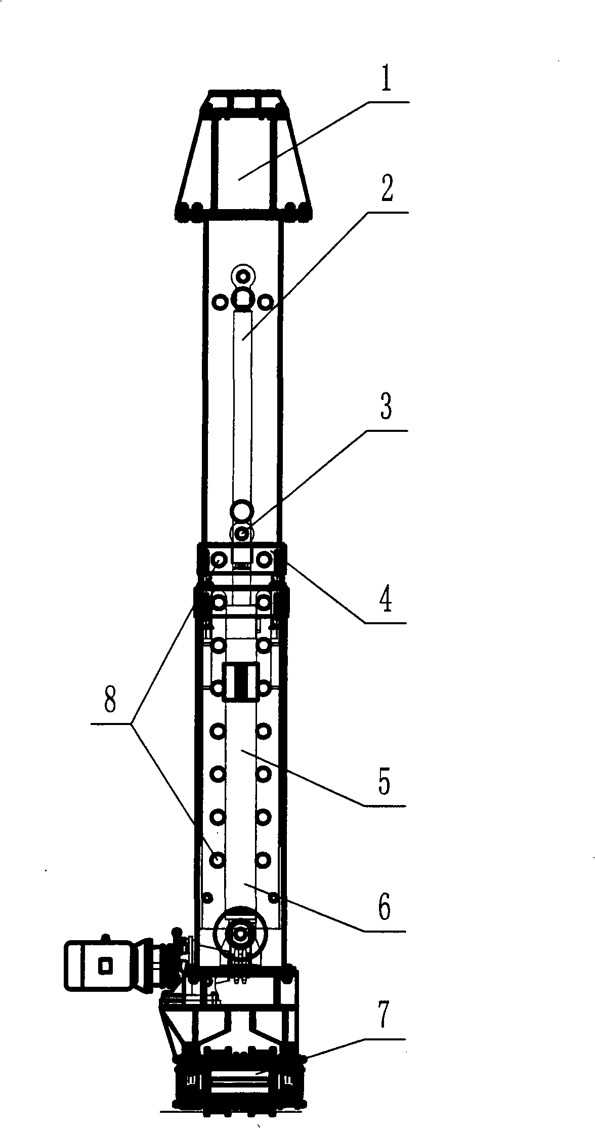
[0040] A. The first and third columns of the pillars include the upper beam 1, the primary guide column 2, the secondary guide column 4, the jacking cylinder 5, the guide bushing 6, and the walking beam 7; the upper beam 1 and the primary guides on both sides The top of the column 2 is fixedly connected; the lower end of the primary guide column 2 is inserted and fixed in the secondary guide column 4; the lower end of the secondary guide column 4 is inserted and fixed in the guide sleeve 6; the lower end of the guide sleeve 6 is fixedly connected to the walking beam 7; The movable end of the lifting cyl...


PUM


Abstract

The invention belongs to a bridge girder erection machine, in particular to a highway-railway bridge girder erection machine. Through adopting the technical proposals that a first column, a third column and a second column are changed into two contracted sections, a horizontal traverse motion is arranged on the third column, etc., the invention solves the problems existing in prior art that the construction site limits the lowest height of the bridge girder erection machine, the girder erecting space of the bridge girder erection machine cannot be ensured, the column base of the third column is suspended when a curved bridge is erected, the third column cannot stand when the bridge girder erection machine passes through the hole, etc. The highway-railway bridge girder erection machine has the advantages that transfer among bridges can be carried out by reducing the height, the machine can pass through a tunnel or a curve tunnel, the transfer time among the bridges can be reduced, the bridge girder erection machine pass through the tunnel more smoothly, the assembly is simpler, etc.

Description

Technical field [0001] The invention belongs to a bridge erecting machine, and particularly refers to a road-rail bridge erecting machine. Background technique [0002] The existing domestic walking telescopic arm type single-guide beam bridge erecting machine (patent number: 01224076.1) is a utility model patent applied for by the applicant in 2001. The above-mentioned prior art has a difference between the highest and lowest position of the bridge erecting machine. Can not effectively guarantee ≥ 3000mm, and can not meet the requirements of the construction site boundary for the minimum height of the bridge erecting machine and the space of the bridge frame beam. The position of the third column is suspended when the bridge is erected when the bridge erecting machine passes through the hole Problems such as the inability to support the third pillar. Summary of the invention [0003] The purpose of the present invention is to provide a road-rail bridge erecting machine, so as t...

Claims


Application Information

Patent Timeline
Patent Type & Authority Applications(China)
IPC IPC(8): E01D21/00
Inventor 王增良李尉东魏学伟阴生富
Owner HANDAN CHINA RAILWAY BRIDGE MACHINERY
Learn More