2-port isolator

An isolator and dual-port technology, applied in waveguide devices, electrical components, circuits, etc., can solve problems such as reducing connection reliability, and achieve the effect of simple assembly and high-precision assembly

Inactive Publication Date: 2008-10-22
HITACHI METALS LTD
View PDF1 Cites 0 Cited by
  • Summary
  • Abstract
  • Description
  • Claims
  • Application Information

AI Technical Summary

Problems solved by technology

If the connection pad becomes smaller, not only is it difficult to reliably connect the center conductor to the connection pad, but also the connection reliability against vibration and shock is reduced due to the reduction in the connection area.

Method used


Image

  • 2-port isolator
  • 2-port isolator
  • 2-port isolator

Examples


Embodiment Construction

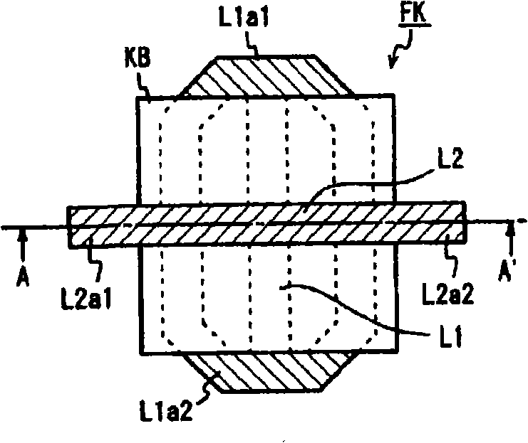
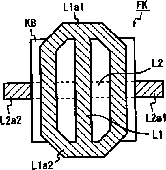
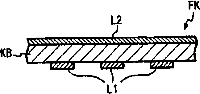
[0040] Figure 4 and Figure 5 The shown two-port isolator has: a square plate-shaped central conductor assembly 3 (having a square-shaped ferrite plate 5, and first and second ferrite plates adjacent to the ferrite plate 5 and configured to intersect in an electrically insulated state. central conductor L1, L2); a multilayer substrate 10 formed with first and second matching capacitors; accommodating the central conductor assembly 3 and the multilayer substrate 10, integrally formed with 6 external parts connected to the mother board (mother board) Resin lower case for terminals IN (P1), OUT (P2), and GND (only referred to as "resin lower case integrated with external terminals") 25; permanent magnet 30 for applying a DC magnetic field to the ferrite plate 5; And the upper case 22 made of magnetic metal that accommodates the permanent magnet 30 and forms a magnetic circuit. The first and second central conductors L1 and L2 are constituted by strip-shaped conductor patterns ...


PUM


Abstract

A 2-port isolator includes a first center conductor connected between a first I / O port and a second I / O port, and second center conductor connected between a second I / O port and the earth which conductors are arranged on a ferrite plate so as to constitute a center conductor assembly. The first and the second center conductor are formed by two band-shaped conductor patterns formed on the both sides of an insulating substrate. The band-shaped conductor patterns intersect each other with a predetermined angle in an insulated state. Their both ends extend from the edge of the insulating substrate and bent so as to cover the side surface of the ferrite plate.

Description

technical field [0001] The present invention relates to a small, high-precision two-port isolator mainly used in microwave bands. Background technique [0002] A non-reciprocal circuit element hardly attenuates a signal in the transmission direction, but greatly attenuates a signal in the reverse direction, and is used, for example, in mobile communication devices such as mobile phones. As such a non-reciprocal circuit element, the most commonly known is Figure 15 isolator shown. This isolator includes: a ferrite (ferrite) plate 38, and three central conductors 31, 32, 33 arranged on one main surface of the ferrite plate 38 in a state of being electrically insulated from each other and intersecting at an angle of 120°. , the ground wire connected to one end of each central conductor 31, 32, 33, each matching capacitor C1-C3 connected to the other end of each central conductor 31, 32, 33, and any one of each central conductor 31, 32, 33 A terminal resistor Rt connected to ...

Claims


Application Information

Patent Timeline
Patent Type & Authority Applications(China)
IPC IPC(8): H01P1/36
CPCH01P1/36
Inventor 寺胁武文野津稔三泽彰规
Owner HITACHI METALS LTD
Why Eureka
Try Eureka