Friction vacuum pump

A technology of vacuum pump and pump stator, applied in the direction of pump, pump element, axial flow pump, etc., to achieve uniform temperature change characteristics and eliminate the effect of assembly work

Inactive Publication Date: 2009-02-04
OERLIKON LEYBOLD VACUUM
View PDF7 Cites 0 Cited by
  • Summary
  • Abstract
  • Description
  • Claims
  • Application Information

AI Technical Summary

Problems solved by technology

The two-part construction of this housing also leads to the aforementioned disadvantages

Method used


Image

  • Friction vacuum pump

Examples


Embodiment Construction

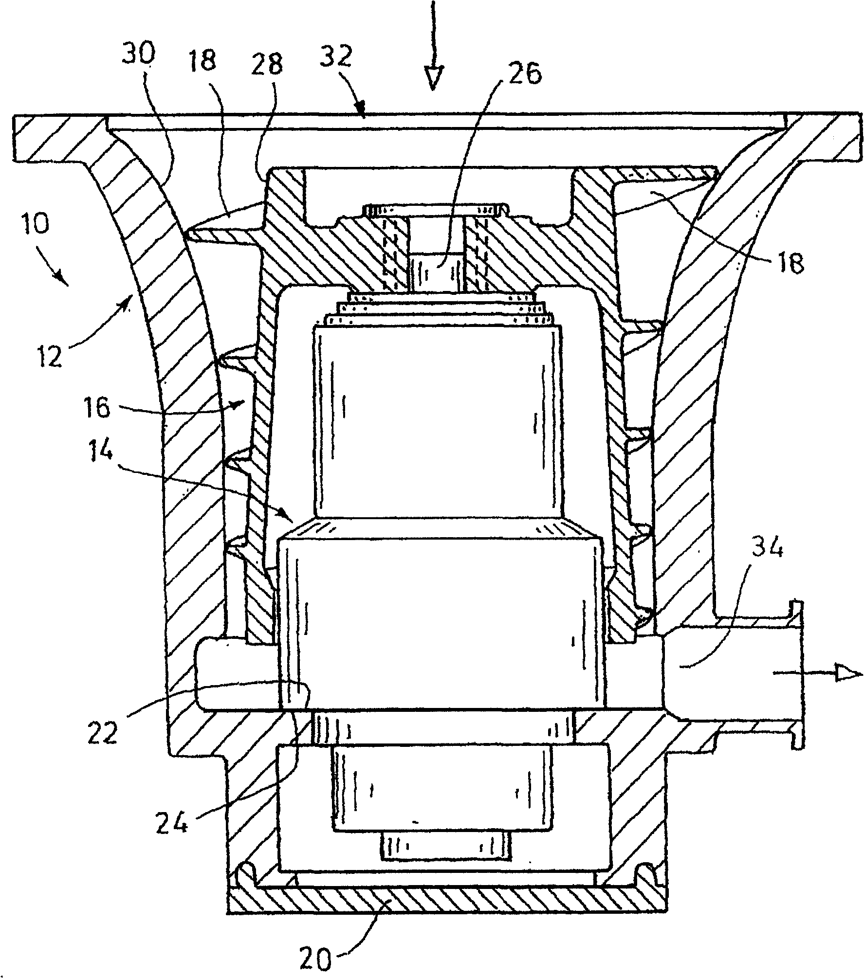
[0017] The drawing shows a friction vacuum pump 10, which is a screw pump, also known as a Holwick pump. The friction vacuum pump 10 basically comprises a housing 12, a cylinder 14 which narrows towards the suction side in a funnel shape, and a pump rotor 16, the cylinder 14 being arranged and fastened in the housing 12 and comprising a not shown rotor holder and The rotor drive, not shown, the pump rotor 16 comprises a plurality of blades 18 arranged helically.

[0018] The housing 12 is of one-piece construction and surrounds the entire axial length of the pump rotor 16 and the barrel 14 including the rotor drive and rotor support. The discharge-side end of the housing 12 is closed by a front-side housing cover 20 .

[0019] In the housing 12 a circumferential shoulder 22 is provided on the inner circumference, on which a corresponding circumferential shoulder 24 of the cartridge 14 is supported gas-tight. The shoulder 22 of the housing 12 and the shoulder 24 of the cartri...


PUM


Abstract

A friction vacuum pump ( 10 ) comprises a housing ( 12 ) defining a vaneless pump stator ( 30 ), a rotor drive and a rotor support which rotatably supports a pump rotor ( 16 ) provided with a vane ( 18 ). The housing ( 12 ) surrounds the overall axial length of the pump rotor ( 16 ), the rotor drive and the rotor support. Prior art housings are of multipart configuration and thus comprise seals between the housing portions. The seals are difficult to coat and may be or become locations where leaks occur. In contrast, the housing ( 12 ) is of one-piece configuration such that, in any case, the region of the housing ( 12 ) which is in contact with the vacuum gas is free of seals.

Description

technical field [0001] The invention relates to a friction vacuum pump comprising a housing constituting a vaneless pump stator, a rotor drive and a rotor support. Background technique [0002] The housing of such a friction vacuum pump, such as a turbomolecular pump or a Holwick pump, surrounds the entire axial length of the pump rotor, rotor drive and rotor carrier. A progressive cavity pump is known from WO 2004 / 015272 A1, the housing of which consists essentially of three axially connected parts which are screwed together to form a housing joint, for example. The three housing parts are the stator housing part, the outlet housing part for supporting the cartridge including the motor and / or bracket and the bearing housing part. In each case a seal is provided between two adjoining housing parts to ensure the required tightness, wherein the seal can be applied with difficulty or not at all, for example with an anti-corrosion coating material. Even the most careful assemb...

Claims


Application Information

Patent Timeline
Patent Type & Authority Patents(China)
IPC IPC(8): F04D19/04F04D29/52F04D29/40
CPCF04D29/644F04D19/044
Inventor 拉尔夫·阿达米茨罗兰·布卢门塔尔迪尔克·卡利施
Owner OERLIKON LEYBOLD VACUUM
Why Eureka
Try Eureka