
System and process for anhydration treatment of wet sludge

A treatment system and treatment process technology, applied in the field of waste treatment devices, can solve the problems of incompleteness, high energy consumption, dehydration of secondary pollution and drying treatment process, etc., achieve high efficiency, good use effect, and improve dehydration and drying performance Effect

Active Publication Date: 2011-07-06
SHENZHEN ECO SOLUTION TECH CORP
View PDF2 Cites 0 Cited by
  • Summary
  • Abstract
  • Description
  • Claims
  • Application Information

AI Technical Summary

Problems solved by technology

[0006] The object of the present invention is to provide a wet sludge drying treatment system and The treatment method solves the problem of sludge resource regeneration with environmental protection, energy saving, high resource utilization rate and low operating cost

Method used


Image

  • System and process for anhydration treatment of wet sludge
  • System and process for anhydration treatment of wet sludge
  • System and process for anhydration treatment of wet sludge

Examples


Embodiment 1

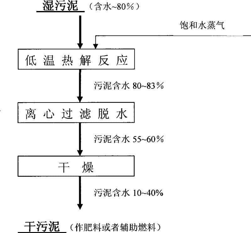
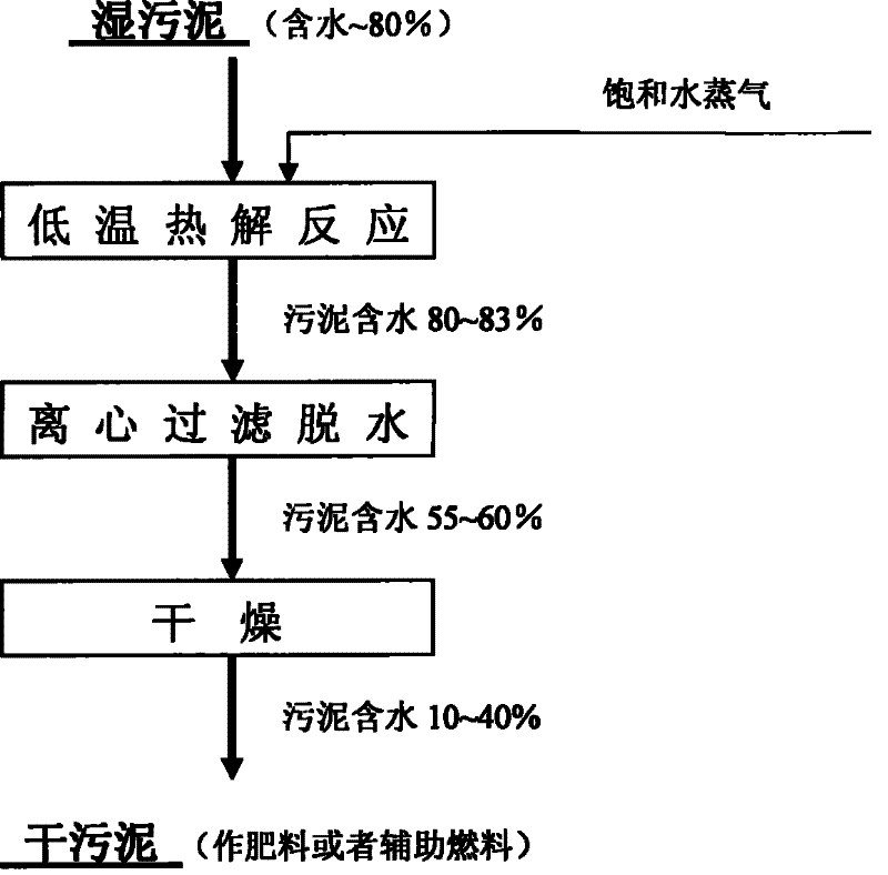
[0033] like figure 1 Shown is a process flow diagram of an embodiment of the wet sludge drying treatment system and process of the present invention. In this process, wet sludge (water content about 80%) is put into a low-temperature pyrolysis reactor, and saturated water vapor with a pressure of 1.5-3.0MPa and a temperature of 150-300°C is introduced into the reactor; the reactor is a closed horizontal A pressure vessel with a stirring device inside; the wet sludge and steam are stirred and mixed evenly in the kettle, and under the action of heat and pressure, the water-holding structure of solid phase substances such as organic polymer structures and colloidal flocs in the sludge is destroyed , to fully release the physical and chemical bound water in the sludge, thereby greatly improving the dehydration and drying performance of the sludge, so that most of the water in the dewatered sludge can be released in the form of liquid water through subsequent mechanical separation...

Embodiment 2

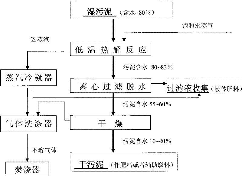
[0037] like figure 2 Shown is a process flow diagram of another embodiment of the wet sludge drying treatment system and process of the present invention. In this process, on the basis of the process flow of embodiment 1, the following process steps have been added:

[0038] Condensate and collect the exhausted steam converted from saturated water vapor in the low-temperature pyrolysis reactor in the condenser;

[0039] The condensed steam and / or gas from the drying and granulation device are collected in the gas scrubber for scrubbing treatment, and the insoluble gas after scrubbing is incinerated.

[0040] At the same time, the condensed liquid produced in the above-mentioned condenser and the filtrate removed by the centrifugal dehydrator can also be collected in the filtrate recovery device to obtain liquid organic fertilizer rich in organic matter.

[0041]Implementing the wet sludge drying treatment system and process of the present invention, compared with the tradit...


PUM


Abstract

The invention relates to a wet sludge anhydration treatment system which comprises a low-temperature pyrolysis reaction device which is used for carrying out the low-temperature pyrolysis reaction of wet sludge and saturated water vapor to convert macromolecular organics in the wet sludge into low-molecular organics, a spiral centrifugal filtering device which is used for carrying out centrifugalfiltering and dehydration to the wet sludge after the pyrolysis in a mechanical separation manner so as to obtain semi-dry sludge with the water content of 55 percent to 60 percent, and a drying device which is used for drying and removing the water in the semi-dry sludge after the filtering and hydration so as to obtain dried-sludge solid fuel with the water content of 10 percent to 40 percent. Meanwhile, the invention also relates to a wet sludge anhydration treatment technology by adopting the treatment system. The system and the technology of the invention can solve the problem of renewable resource of sludge in a method of environment protection, energy saving, high resource utilization and low operating cost.

Description

[0001] field of invention [0002] The invention relates to a waste treatment device and process, in particular to a wet sludge drying treatment system and treatment process. Background technique [0003] Wet sludge is a by-product produced in the process of sewage treatment. The composition of sludge is extremely complex, mainly containing about 80-90% water, and other organic matter that can be recycled, various organic matter, various trace elements, and possible environmental pollution. Pathogenic microorganisms, parasite eggs, heavy metals, etc. that cause adverse effects. The harmless and resourceful treatment of wet sludge is an important topic of ecological environment protection worldwide. [0004] Traditional wet sludge treatment methods include throwing into the sea (or direct discharge), landfilling and composting, but there are negative impacts on the environment (water pollution, soil pollution and air pollution, etc.) and space resources (land and water fields...

Claims


Application Information

Patent Timeline
Patent Type & Authority Patents(China)
IPC IPC(8): C02F11/10C02F11/12C02F11/16C05G1/00C10L8/00B09B3/00
CPCY02W30/20
Inventor 黄彤宇张林铃木德彦
Owner SHENZHEN ECO SOLUTION TECH CORP
Learn More