Multiple-channel transmit magnetic resonance

A magnetic resonance, multi-channel technology, applied in the direction of magnetic resonance measurement, measurement of magnetic variables, measurement devices, etc., can solve the problem of impractical exhaustive search, and achieve the effects of improving image quality, reducing SAR, and improving uniformity

Inactive Publication Date: 2008-10-08
KONINKLIJKE PHILIPS ELECTRONICS NV
View PDF0 Cites 14 Cited by
  • Summary
  • Abstract
  • Description
  • Claims
  • Application Information

AI Technical Summary

Problems solved by technology

Even with a high-speed supercomputer, 10 20 An exhaustive search of such combinations is also impractical

Method used


Image

  • Multiple-channel transmit magnetic resonance
  • Multiple-channel transmit magnetic resonance
  • Multiple-channel transmit magnetic resonance

Examples


Embodiment Construction

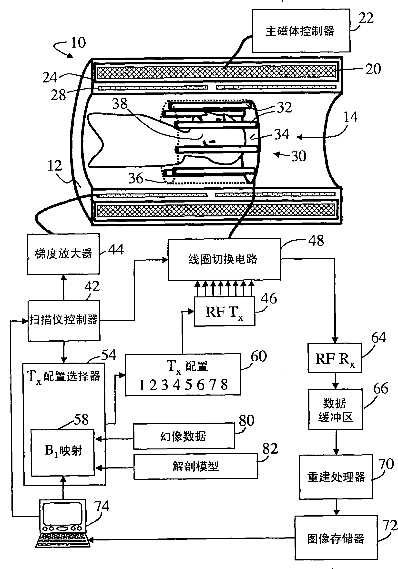
[0022] see figure 1 , the magnetic resonance scanner 10 includes a scanner housing 12 that includes a bore 14 or other receiving area for receiving a patient or other subject. A main magnet 20 placed in the scanner housing 12 is controlled by a main magnet controller 22 for generating a main magnetic field B in the examination region within the bore 14 0 . Typically, the main magnet 20 is a permanent superconducting magnet surrounded by cryoshrouding 24, however, for lower B 0 Field strength can be used with resistive or permanent main magnets.

[0023] Magnetic field gradient coils 28 are arranged in or on the housing 12 in order to superimpose selected magnetic field gradients on the main magnetic field at least in the examination region. Typically, magnetic field gradient coils include coils for generating three orthogonal magnetic field gradients (eg, x-gradient, y-gradient, and z-gradient). TEM transmit / receive (T / R) radio frequency coil 30 for injection B 1 RF excit...


PUM


Abstract

In a transmit apparatus, a multi-channel radio frequency transmitter (30, 46) includes a plurality of transmit elements (32) defining at least two independently operable transmit channels. A transmit configuration selector (54) determines a selected transmit configuration (60) specifying amplitude and phase applied to each transmit channel to generate a B1 field in a corresponding selected region (90) of a subject (38) coupled with the radio frequency transmitter. The transmit configuration selector determines the selected transmit configuration based on B1 mapping (58) of the subject and a B1 field quality assessment employing at least two different B1 field quality measures.

Description

technical field [0001] The invention relates to the field of magnetic resonance. In particular, the present invention is used in conjunction with magnetic resonance imaging using transverse electromagnetic (TEM) coils in which rods or selected groups of rods operate independently as transmit channels, as described in more detail below. Broadly speaking, the present invention is used in conjunction with a radio frequency (RF) transmitter for generating magnetic resonance comprising multiple transmitting elements (e.g., the aforementioned TEM coil rod or degenerate birdcage coil meshes or surface transmit coils, etc.), said transmit elements defining at least two independently operable transmit channels for use in magnetic resonance spectroscopy, magnetic resonance imaging, etc. Background technique [0002] Magnetic resonance imaging, magnetic resonance spectroscopy, etc. are typically performed in static magnetic fields of between about 0.5 Tesla and about 7 Tesla, with hig...

Claims


Application Information

Patent Timeline
IPC IPC(8): G01R33/32G01R33/3415
CPCG01R33/5612G01R33/246G01R33/3415
Inventor Z·翟M·A·莫里希G·D·德梅斯特
Owner KONINKLIJKE PHILIPS ELECTRONICS NV
Why Eureka
Try Eureka