Eureka AIR delivers breakthrough ideas for toughest innovation challenges, trusted by R&D personnel around the world.

Method for transmitting data by sharing relay station

A technology for sending data and relay stations, applied in the field of two-hop relay networks, can solve the problems of reducing spectrum utilization, allocating the same resource to RS, and existing defects, and achieves improved spectrum utilization, simple and clear frame structure, and small delay. Effect

Inactive Publication Date: 2008-10-08
如皋市华灿置业有限公司
View PDF0 Cites 3 Cited by
  • Summary
  • Abstract
  • Description
  • Claims
  • Application Information

AI Technical Summary

Problems solved by technology

This frame structure uses scheduling to make the resources of RS not conflict, but there are defects
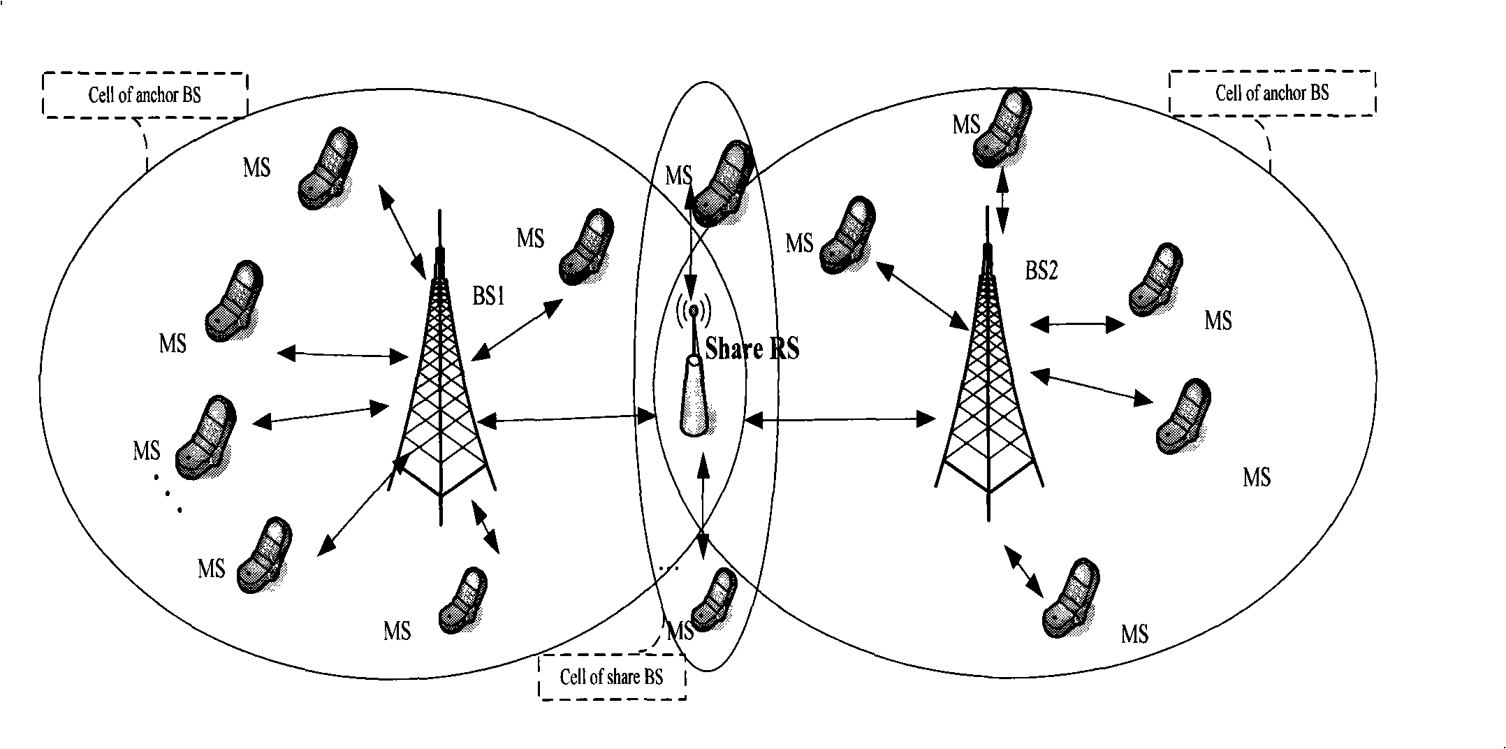
[0008] For a shared RS system (which is characterized by the RS located in the overlapping area of ​​two MR-BS coverage), in order to avoid the collision of the relay link on the shared RS, some scheduling rules need to be considered: each MR-BS needs to determine the resource allocation The same resource cannot be allocated to the RS at the same time; in order to avoid collisions, each MR-BS should allocate the same shared RS in different frames, so that although the communication quality between the RS and the BS and the MS to which it belongs is guaranteed, but because The presence of a shared RS reduces the spectrum utilization of another BS

Method used


Image

  • Method for transmitting data by sharing relay station
  • Method for transmitting data by sharing relay station
  • Method for transmitting data by sharing relay station

Examples


Embodiment Construction

[0030] The technical solutions of the present invention will be further described below in conjunction with the accompanying drawings and through specific implementation methods.

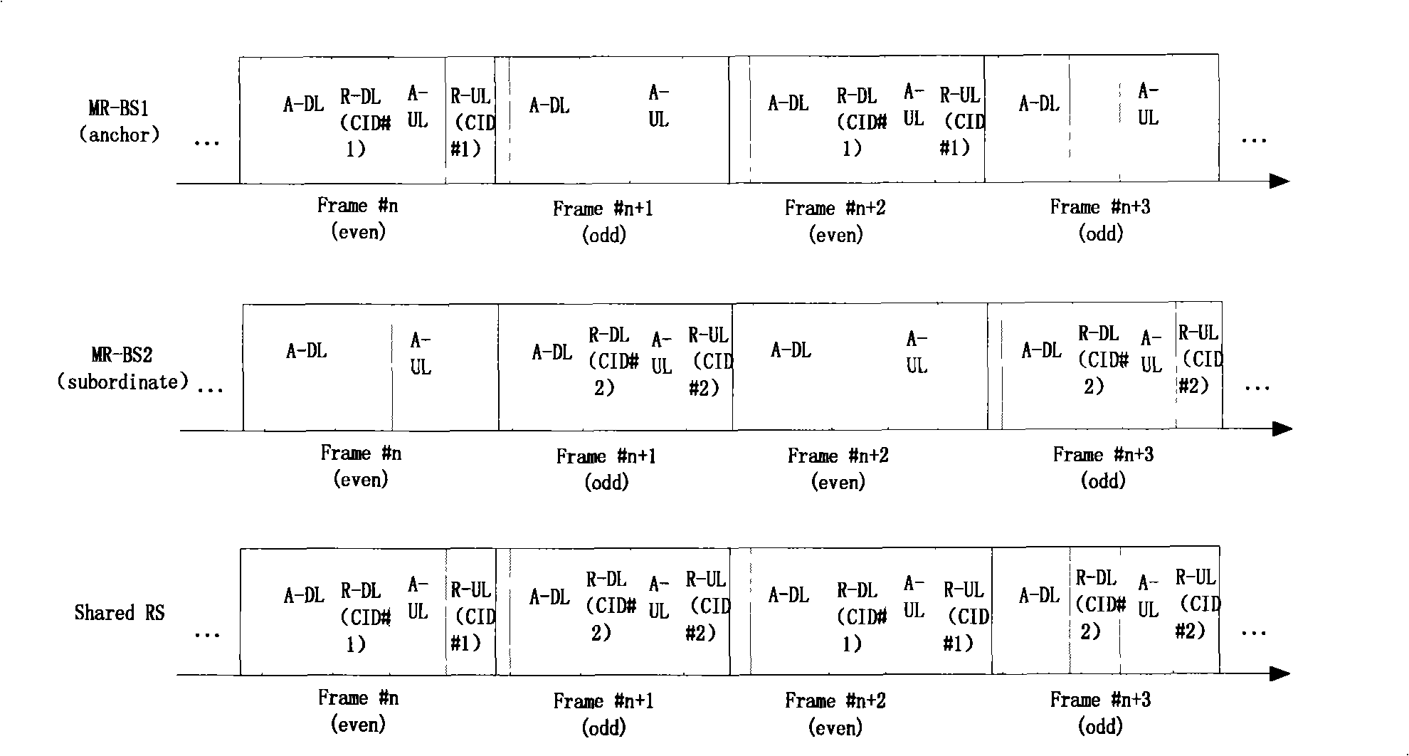
[0031] Each of the anchor BS and subordinate BS includes a downlink subframe and an uplink subframe. The downlink subframe of the anchor BS is divided into a DL Access Zone, an Optional DL Access Zone and an Optional DL Relay Zone. DL Access Zone is a necessary part of the downlink subframe, used for MR-BS transmission to MS; Optional DL Access Zone is an optional part of the downlink subframe, used for MR-BS to transmit to some MSs; Optional DL Relay Zone is the downlink A part of the subframe used for transmission from MR-BS to RS. The DL Access Zone precedes the Optional DL Access Zone in time, which precedes the Optional DL Relay Zone.

[0032] The anchor BS uplink subframe is divided into a UL Access Zone, an Optional UL AccessZone and an Optional UL Realy Zone. UL Access Zone is a mandatory...


PUM


Abstract

The present invention discloses a method for transmitting data through a relay station. In the transmission process of the descending data, an anchor transmits data to a mobile terminal through a DL Access Zone, and transmits data to the relay station through an Optional DL Relay Zone. A subordinate BS transmits data to the mobile terminal through the DL Access Zone, and transmits data to the relay station through the Optional DL Relay Zone. In the transmission process of the ascending data, the mobile terminal transmits data to the anchor BS / RS through an UL Access Zone. A sharing RS transmits data to the anchor BS through an Optical UL Relay Zone. The mobile terminal transmits data to the subordinate BS through an UL Access Zone. The sharing RS transmits data to the subordinate BS through an Optional UL Relay Zone. The technical scheme according to the invention can increase the usage of frequency spectrum at the state that the resource of RS can be scheduled.

Description

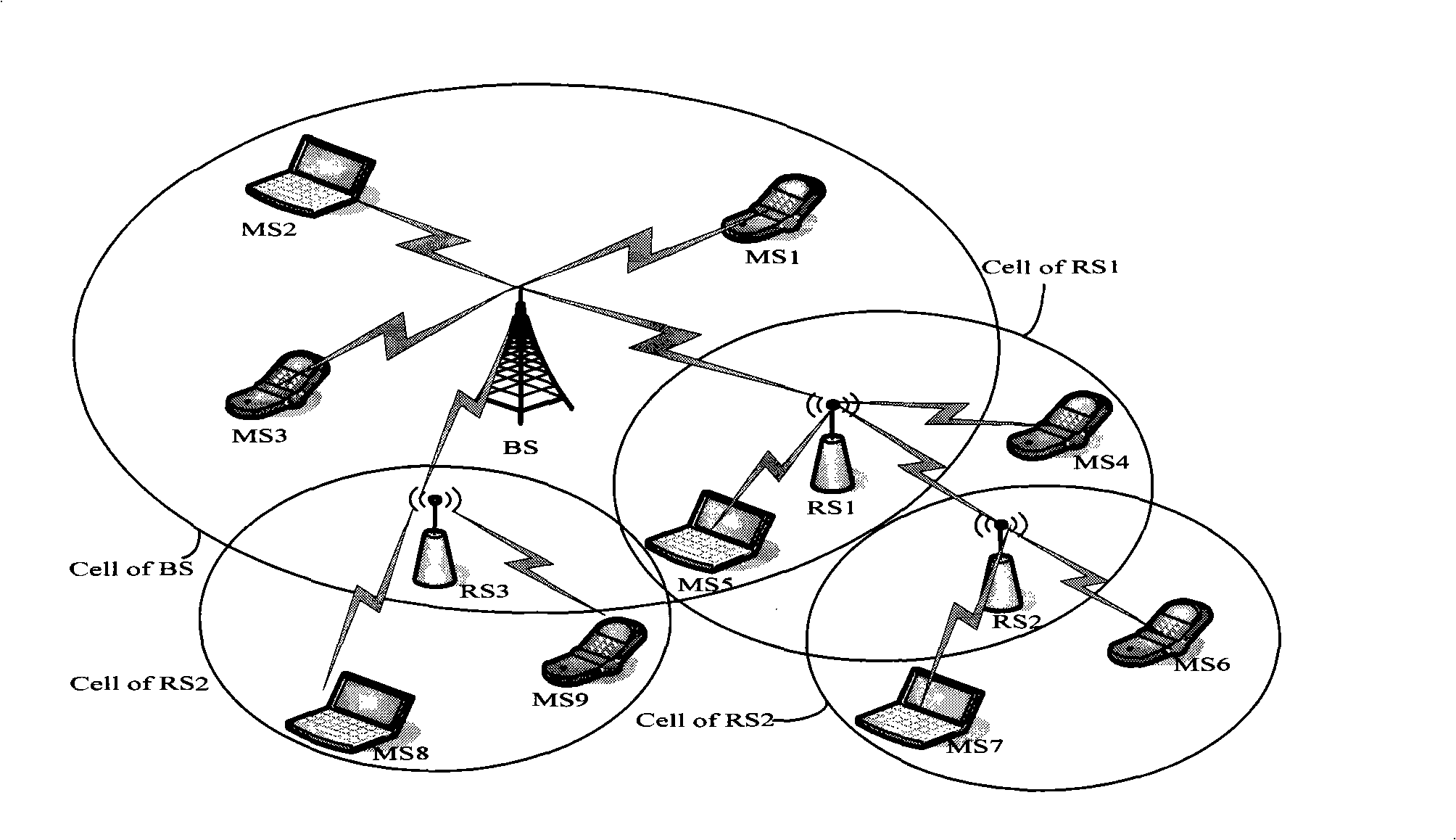
technical field [0001] The invention relates to the technical field of two-hop relay networks, in particular to a method for sending data through a shared relay station. Background technique [0002] The standard IEEE 802.16j introduces a relay station (Relay Station, RS) on the basis of IEEE 802.16e. In many proposals of IEEE 802.16j, RS is divided into fixed RS, nomadic RS and mobile RS (referred to as MRS), and a base station (Base Station, BS) with one or more RS is called MR-BS, and a mobile terminal ( Mobile Station, MS) can directly communicate with MR-BS, and can also communicate with MR-BS through one or more levels of RS. [0003] figure 1 It is a schematic diagram of the network topology of MR-BS, RS and MS. Such as figure 1 As shown, the signal transmission between the BS and the MS is completed through one or several stages of relays. There are two goals for setting RS in MMR: one is to expand coverage or cover blind spots; the other is to increase system c...

Claims


Application Information

Patent Timeline
IPC IPC(8): H04B7/14H04B7/26
Inventor 刘巧艳赵路余秋星
Owner 如皋市华灿置业有限公司
Why Eureka
Eureka Blog
Learn More