
Method and device for reducing temperature error of magnetic resonance temperature imaging

A temperature error and magnetic resonance technology, applied in the field of magnetic resonance imaging image processing, can solve the problems of difficult to obtain stable, consistent and accurate results, and difficult to monitor temperature changes, so as to reduce treatment time, reduce temperature errors, and reduce Effects of small complexity

Inactive Publication Date: 2008-10-01
SIEMENS AG
View PDF0 Cites 12 Cited by
  • Summary
  • Abstract
  • Description
  • Claims
  • Application Information

AI Technical Summary

Problems solved by technology

The temperature change monitored by this method is limited to the vicinity of the HIFU focus, and it is difficult to monitor the temperature change outside the focus in practical applications
In addition, the accuracy of fitting extrapolation is related to the complexity of the phase map and the size of the heating area, and it is not easy to obtain stable and accurate results in the application

Method used


Image

  • Method and device for reducing temperature error of magnetic resonance temperature imaging
  • Method and device for reducing temperature error of magnetic resonance temperature imaging
  • Method and device for reducing temperature error of magnetic resonance temperature imaging

Examples


Embodiment 1

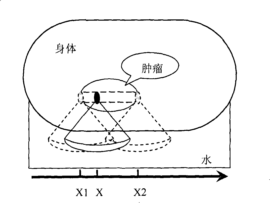
[0034] In this embodiment, it is assumed that the treatment head moves in a one-dimensional direction. figure 1 It is a schematic diagram of the HIFU treatment head moving in one-dimensional direction. Such as figure 1 As shown, when the treatment head is not heated, the treatment head moves to the positions X1 and X2, and the reference images Img_r1 and Img_r2 are collected respectively. When the treatment head moves to the position X, the image Img is heated and collected.

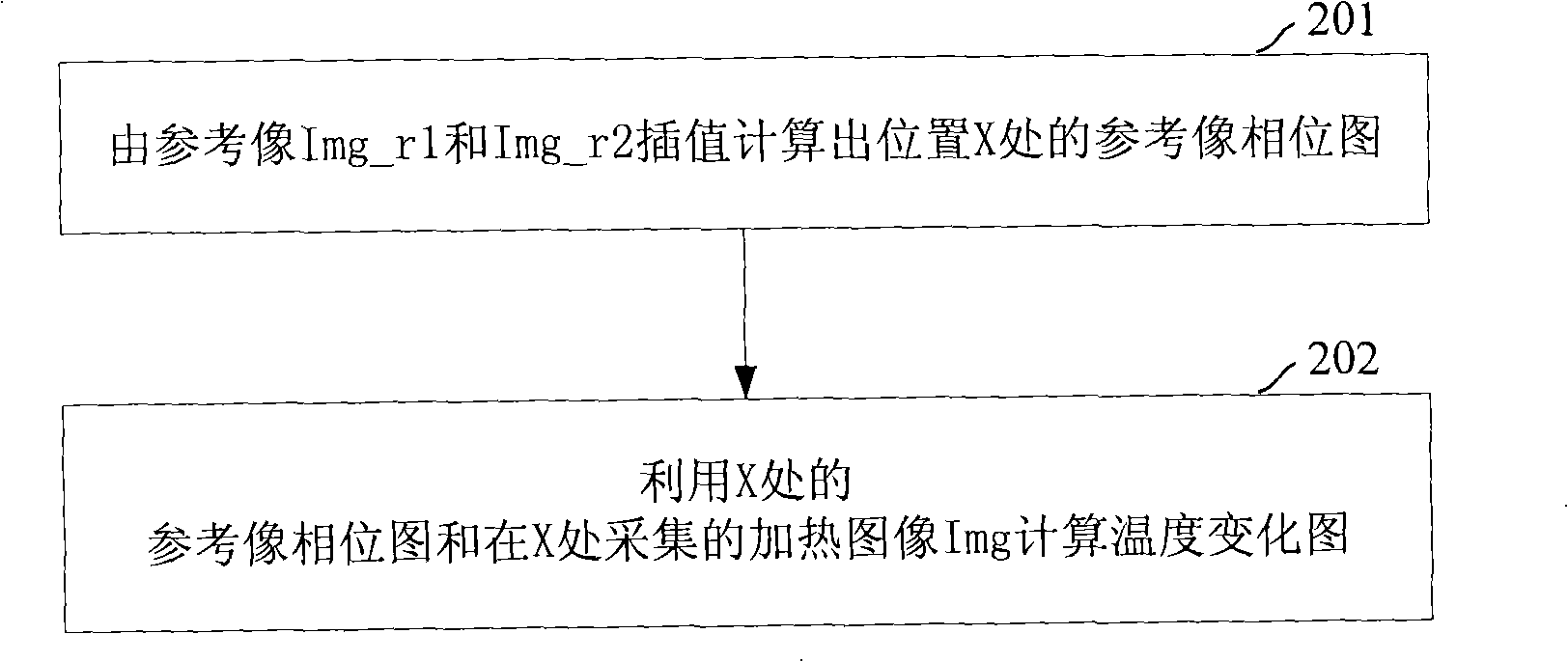
[0035] figure 2 It is a flowchart of a method for reducing temperature errors in magnetic resonance temperature imaging according to Embodiment 1 of the present invention. Such as figure 1 As shown, in this embodiment, the method for reducing temperature errors in magnetic resonance temperature imaging includes the following steps:

[0036] Step 201, calculate the phase map of the reference image at position X by interpolation from the reference images Img_r1 and Img_r2.

[0037] If Φ_r1 is used to...

Embodiment 2

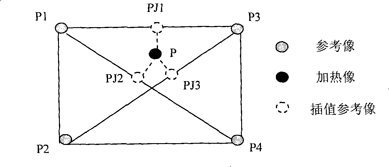
[0046] In this embodiment, the treatment head moves in two dimensions. When not heated, multiple reference images are collected at different positions of the treatment head, and the positions of these reference images should be scattered within the range of treatment movement of the treatment head as much as possible. image 3 It is a schematic diagram of the HIFU treatment head moving in the two-dimensional direction. Such as image 3 As shown, when not heated, the treatment head collects reference images Img_r1, Img_r2, Img_r3 and Img_r4 at positions P1, P2, P3 and P4 respectively, and when the treatment head moves to position P, it heats and collects the image Img.

[0047] Figure 4 It is a flowchart of a method for reducing temperature errors in magnetic resonance temperature imaging according to Embodiment 2 of the present invention. Such as Figure 4 As shown, in this embodiment, the method for reducing temperature errors in magnetic resonance temperature imaging in...


PUM


Abstract

The invention discloses a method for reducing the temperature error in magnetic resonance temperature imaging, which is used for the high-intensity focused ultrasound HIFU treatment monitored by magnetic resonance, the method comprises that: a reference image which is generated on two or more positions by an HIFU treatment head is carried out the interpolation, thus obtaining the reference image of the moving position of the HIFU treatment head; and the temperature change of a heating region is calculated according to a phase diagram of the interpolated reference image of the moving position of the HIFU treatment head and a heating image which is generated at the position by the HIFU treatment head. The invention further discloses a device for reducing the temperature error in the magnetic resonance temperature imaging, which comprises a reference image interpolation unit and a temperature calculation unit. The usage of the method and the device of the invention can significantly reduce the temperature error which is caused by the change of the magnetic susceptibility during the movement of the HIFU treatment head, which can not only obtain the accurate temperature change of the heating region, but also can reduce the complexity of the operation and the treatment time of the HIFU treatment.

Description

technical field [0001] The present invention relates to magnetic resonance imaging (MRI, Magnetic Resonance Imaging) image processing technology, in particular to a method for reducing temperature errors in magnetic resonance temperature imaging and a corresponding device. Background technique [0002] Magnetic resonance (MR, Magnetic Resonance) proton resonance frequency (PRF, Proton Resonance Frequency) thermometry can be used to monitor changes in the temperature of the treatment site during MR-monitored high-intensity focused ultrasound (HIFU, High Intensity Focused Ultrasound) treatment. The principle is to use the resonance frequency of protons in water to shift with the change of temperature. The PRF method requires the generation of a baseline image (baseline image) before heating, also known as a reference image, which provides reference phase information, which is used to subtract the phase image obtained during or after heating to determine The exact value of the...

Claims


Application Information

Patent Timeline
IPC IPC(8): A61B5/055A61N7/00G01R33/48G06T5/00
Inventor 周晓东戴勇鸣
Owner SIEMENS AG
Learn More