
Lange coupler bridle wire structure and implementing method

An implementation method and a coupler technology, applied in the field of couplers, can solve the problems of difficult implementation, easy falling off of gold wires, unfavorable rapid production, etc., and achieve the effects of simple implementation method, good anti-vibration effect and excellent electrical performance.

Inactive Publication Date: 2008-09-24
HANGZHOU JOINTCOM COMM TECH
View PDF0 Cites 4 Cited by
  • Summary
  • Abstract
  • Description
  • Claims
  • Application Information

AI Technical Summary

Problems solved by technology

The usual practice is to weld a gold wire jumper with a gold wire pressure welding machine, which is difficult to achieve in civilian use
Mainly reflected in: firstly, the cost of the gold wire bonding machine and gold wire used is relatively high, and the printed board needs to be specially treated, so that the market competitiveness of the product is not enough; secondly, the training requirements for assemblers are relatively high , which is not conducive to mass and rapid production; finally, the gold wire is easy to fall off or loose after being collided, which is risky for ensuring device performance indicators and power capacity

Method used


Image

  • Lange coupler bridle wire structure and implementing method
  • Lange coupler bridle wire structure and implementing method
  • Lange coupler bridle wire structure and implementing method

Examples


Embodiment 1

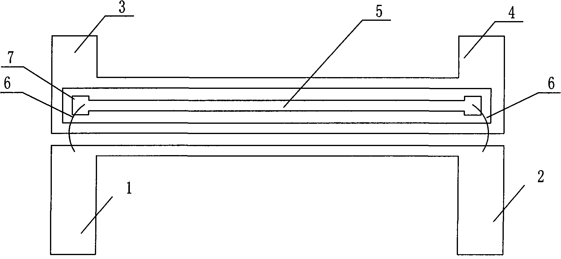
[0017] Embodiment 1: as figure 1 As shown, the Lange coupler jumper structure mainly includes an input port 1, a through port 2, a coupling port 3 and an isolation port 4, and the input port 1, the through port 2, the coupling port 3 and the isolation port 4 are respectively connected to The copper wires 5 are connected, and a jumper 6 for connection is provided between the copper wires 5 , and a pad 7 is provided at the connection between the jumper 6 and the copper wire 5 . The coupling port 3 and the isolation port 4 form an inner cavity, and the input port 1 and the through port 2 are respectively connected to the copper wire segment in the inner cavity through a jumper wire 6 .

Embodiment 2

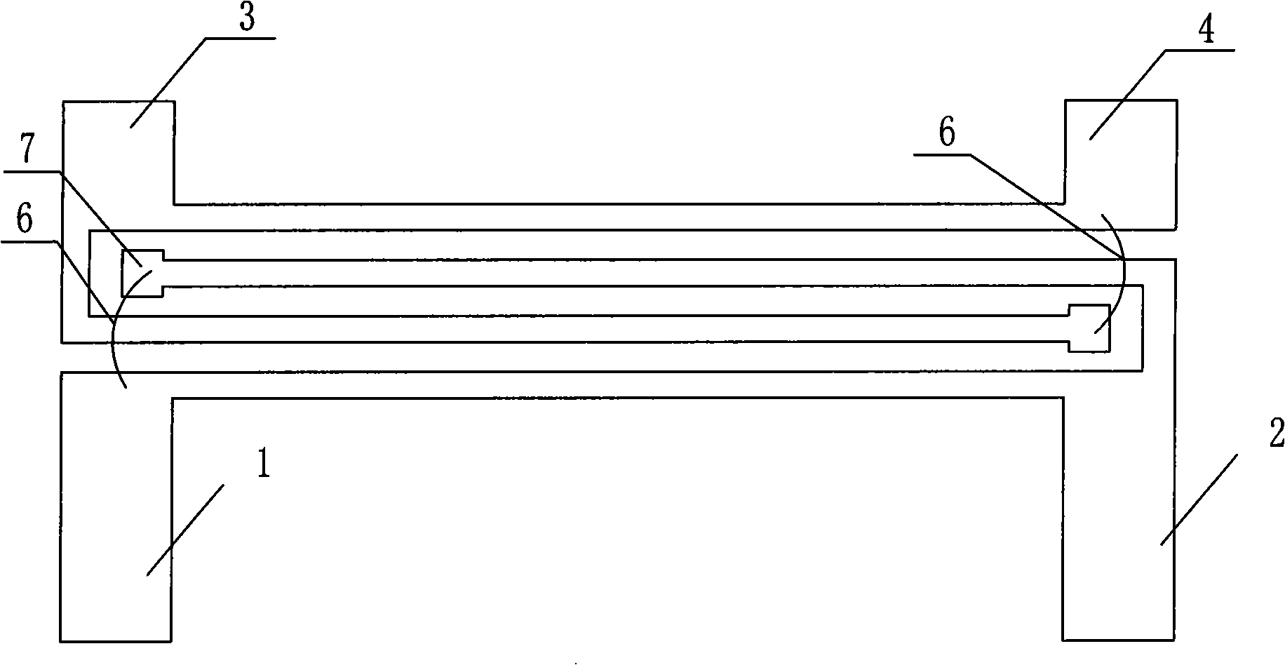
[0018] Example 2, as figure 2 As shown, the copper wire of the input port 1 is connected with the copper wire of the through port 2 through the jumper 6, and the copper wire of the input port 1 is connected with the copper wire of the isolation port 4 through the jumper 6.

Embodiment 3

[0019] Example 3, such as image 3 As shown, the copper wire of the input port 1 is connected to the copper wire of the through port 2 through a jumper 6 , and the copper wire of the coupled port 3 is connected to the copper wire of the isolation port 4 through a jumper 6 .


PUM


Abstract

The invention relates to a jumper structure of a Lange coupler, which substantially comprises an input port, a throughway port, a coupling port and an isolate port. The input port, the throughway port, the coupling port and the isolate port are respectively connected with a copper wire; a jumper used for connecting is arranged between the copper wires; a bonding pad is arranged at the joint of the jumper and the copper wire. The Lange coupler jumper can be realized by the following method and steps: a printed plate is arranged according to the junction of the input port, the throughway port, the coupling port and the isolate port and is assembled in a circuit box; the bonding pad is arranged at the positions where the jumper is required, the jumper is welded on a circuit printed board by an electric iron. The jumper structure has the advantages that the adoption of the copper wire taking the place of a spun gold and the bonding pad jumper structure can realize the Lange coupler manufactured by an ordinary printed plate process, which gains better effect; the jumper also has the advantages of excellent electrical properties, simple structure, simple implement method, comparatively small volume, good anti-vibration effect and good high and low temperature indexes and so on.

Description

technical field [0001] The invention relates to the field of couplers, and mainly relates to a Lange coupler jumper structure and a realization method. Background technique [0002] The Lange coupler is a classic implementation of tightly coupled microstrip circuits, and it has the advantages of wide frequency bandwidth, small phase error, high directivity and low standing wave ratio. The usual practice is to weld a gold wire jumper with a gold wire pressure welding machine, which is difficult to achieve in civilian use. Mainly reflected in: firstly, the cost of the gold wire bonding machine and gold wire used is relatively high, and the printed board needs to be specially treated, so that the market competitiveness of the product is not enough; secondly, the training requirements for assemblers are relatively high , which is not conducive to mass and rapid production; finally, the gold wire is easy to fall off or loose after being collided, which poses a risk to ensure dev...

Claims


Application Information

Patent Timeline
IPC IPC(8): H01P5/00H01P5/12H01P11/00H05K1/18
Inventor 陈玉兵张需溥马欢徐江云
Owner HANGZHOU JOINTCOM COMM TECH
Learn More