
Combustion driven three-dimensional physical analogue device

A physical simulation and three-dimensional technology, applied in teaching models, production fluids, instruments, etc., can solve the problems that affect the development prospect of fire flooding oil recovery technology, cannot explore the fire flooding mechanism in depth, and has little guiding role in on-site reservoir management. Achieve the effects of wide distribution of measuring points, easy maintenance, and strong safety and reliability

Inactive Publication Date: 2010-07-21
RES INST OF PETROLEUM ENG SHENGLI OIL FIELD SINOPEC
View PDF0 Cites 0 Cited by
  • Summary
  • Abstract
  • Description
  • Claims
  • Application Information

AI Technical Summary

Problems solved by technology

[0002] The currently used combustion displacement physical simulation device adopts a long cylindrical structure, which can simulate the combustion displacement situation, but it also has the following shortcomings or deficiencies: ① only one-dimensional simulation experiments can be carried out, and the research parameters are limited to the basic combustion parameters of the oil layer , such as: crude oil ignition point, fuel content, H / C ratio, air consumption, one-dimensional simulated recovery factor, etc.; ② can only study the axial propulsion law of the fire front, and cannot evaluate the planar propulsion and distribution of the fire front ③The mechanism of combustion flooding cannot be deeply explored, and it has little guiding effect on on-site reservoir management, which directly affects the development prospect of combustion oil recovery technology

Method used


Image

  • Combustion driven three-dimensional physical analogue device
  • Combustion driven three-dimensional physical analogue device
  • Combustion driven three-dimensional physical analogue device

Examples


Embodiment Construction

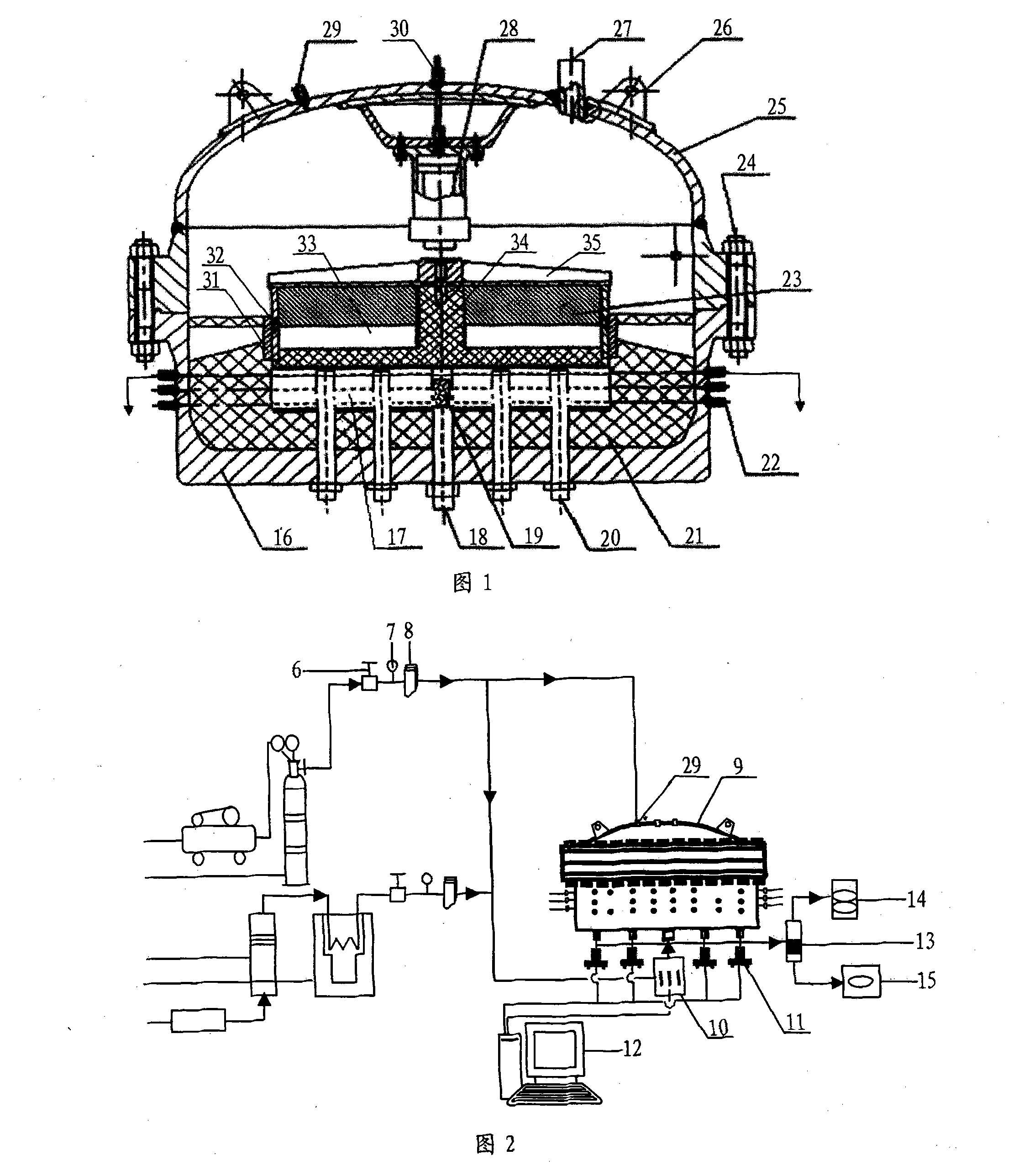
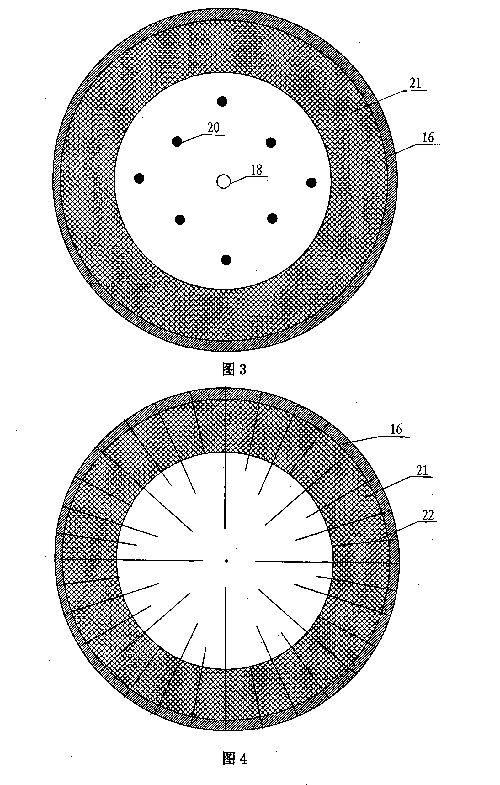
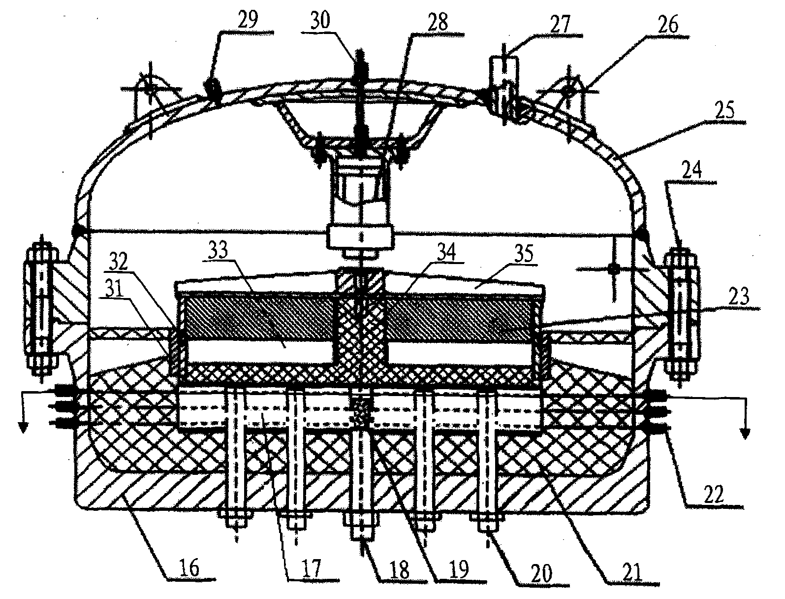
[0016] Referring to Fig. 1-Fig. 4, a three-dimensional physical simulation device for oil displacement by combustion includes an injection system, a simulation body, a measurement and control system and an output analysis system. The injection system includes an air compressor 1, a pressure regulator bottle 2, an injection pump 3, a steam Generator 5, flow meter 8 and intermediate piston container 4, measurement and control system, including thermocouple 22, injection well temperature, pressure, flow collector 10, production well differential pressure sensor 11, computer and its interface circuit 12, output analysis system , including a production fluid recovery device 13, an online gas analyzer 14 and an electronic balance 15, the analog body 9 is connected with the injection system, the measurement and control system and the output analysis system, and the analog body includes a main body 16 and a fixed cover 25 , the thermal insulation body 21 installed at the bottom of the ...


PUM


Abstract

The invention relates to a three-dimensional physical simulation device for a combustion drive, comprising an injecting system, a simulation body, a measurement and control system and an output analysis system. The injecting system consists of an air compressor, a pressure-stabilizing bottle, an injection pump, a steam generator, a flow meter and a middle piston container; the measurement and control system consists of a thermocouple, a temperature of an injection well, a pressure, a flow collector, a differential pressure transducer of an output well, a computer and an interface circuit thereof; the output analysis system consists of a produced fluid recoverer, a gas online analyzer and an electronic balance; the simulation body is connected with the injection system, the measurement andcontrol system and the output analysis system and consists of the body, a close cover which is fixed with the body into a whole, a thermal insulator arranged on the bottom of a cavity in the body, and an experimental oil layer, a spacing ring and a piston assembly which are arranged in the cavity of the thermal insulator in sequence; a five-point type flooding well network, the nine-point type flooding well network and at least one layer of the thermocouple are arranged in the experimental oil layer; the hydraulic pressure cylinder is perpendicular to the piston assembly and arranged on the top of the close cover.

Description

1. Technical field [0001] The invention relates to an indoor test device for oil thermal recovery fire displacement technology, in particular to a three-dimensional physical simulation device for fire displacement. 2. Background technology [0002] The currently used combustion displacement physical simulation device adopts a long cylindrical structure, which can simulate the combustion displacement situation, but it also has the following shortcomings or deficiencies: ① only one-dimensional simulation experiments can be carried out, and the research parameters are limited to the basic combustion parameters of the oil layer , such as: crude oil ignition point, fuel content, H / C ratio, air consumption, one-dimensional simulated recovery factor, etc.; ② can only study the axial propulsion law of the fire front, and cannot evaluate the planar propulsion and distribution of the fire front (3) It is impossible to deeply explore the mechanism of combustion flooding, which has litt...

Claims


Application Information

Patent Timeline
Patent Type & Authority Patents(China)
IPC IPC(8): G09B25/00G09B25/02E21B43/243
Inventor 王世虎谢志勤关文龙曹钧合杜永欣蔡文斌李友平李淑兰白艳丽
Owner RES INST OF PETROLEUM ENG SHENGLI OIL FIELD SINOPEC
Learn More