
Thermal control device on board a spacecraft

一种热控制、航天器的技术,应用在宇宙航行飞行器生活条件控制的装置、宇宙航行的飞行器、飞行器等方向,能够解决散热器低、影响散热器尺寸、限制布置等问题

Inactive Publication Date: 2008-09-24
THALES SA
View PDF0 Cites 25 Cited by
  • Summary
  • Abstract
  • Description
  • Claims
  • Application Information

AI Technical Summary

Problems solved by technology

The heat sink (conventional or deployable) must operate at a temperature lower than the maximum acceptable temperature of the equipment to be controlled, which greatly affects the required size of the heat sink, thereby limiting its use in satellite Possibility of placing

Method used


Image

  • Thermal control device on board a spacecraft
  • Thermal control device on board a spacecraft
  • Thermal control device on board a spacecraft

Examples


Embodiment Construction

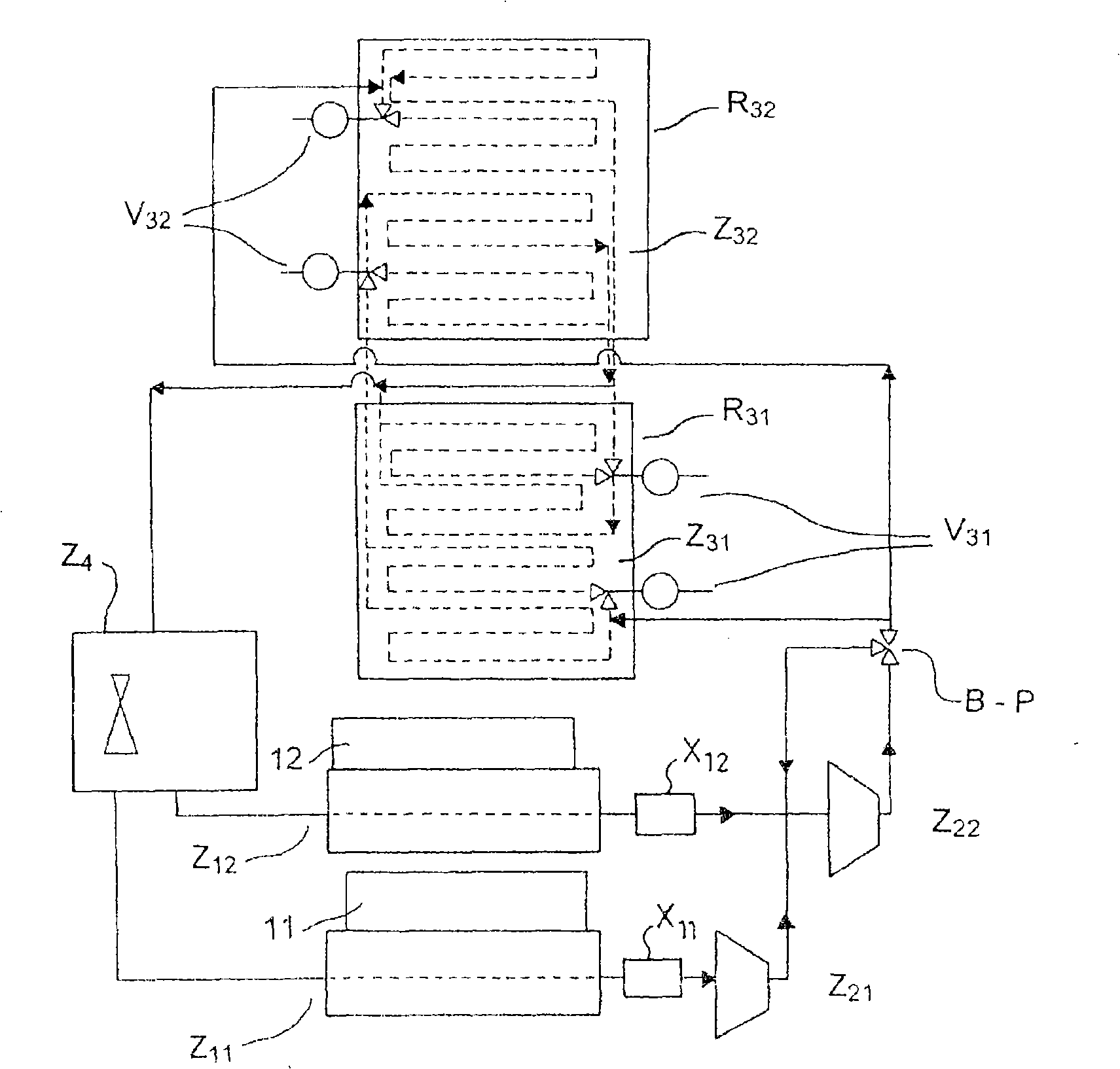
[0031] The device of the present invention consists of figure 1 Schematically shown, which includes the evaporation zone Z 1 , compression zone Z 2 , condensation area Z 3 and decompression zone Z 4 , and a refrigerant circulator.

[0032] More precisely, it consists, first of all, of employing a refrigerant to absorb the heat dissipation belonging to the satellite or to several elements of the satellite (evaporation zone Z of the device 1 ), and then compress the resulting vapor (the refrigerant in the compression zone Z 2 cycle), and thus the refrigerant temperature rises. At the outlet of the compression area of ​​the device, the refrigerant condenses on a dedicated heat dissipation panel (the condensation area Z of the device 3 ), which dissipate the total energy into cold space by dissipating heat at high temperature. These cooling panels are thermally, conductively and radiatively separated from the supporting structure of the device, allowing the temperature of t...


PUM


Abstract

The invention relates to a thermal control device intended to dissipate the heat generated by a payload on a spacecraft, comprising a number of surfaces and including means for circulating a refrigerant. An evaporation zone (Z1) comprises means for circulating the refrigerant, a compression zone (Z2), a condensation zone (Z3) comprising at lEast one radiating panel, linked to a part of the means for circulating the refrigerant, including several branches and comprising means to allow or inhibit the circulation of the refrigerant within these branches so as to vary the area of the heat exchange surface in the condensation zone, a pressure reduction zone (Z4) comprising means for circulating the refrigerant. Such a device is particularly well adapted to thermal problems encountered in telecommunications satellites.

Description

technical field [0001] The present invention relates to a thermal control device mounted on a satellite, more generally a spacecraft. Background technique [0002] generally speaking, satellites include a series of equipment elements that generate heat when they are in operation, and this heat must be efficiently removed to the cold space of space to keep the temperature of these equipment within the routine temperature range . Typically, heat pipes are proposed to transfer heat generated by spacecraft equipment. The heat pipe transfers thermal energy toward the heat sink. If the heat pipes form a fluid circuit, after the emission state, the heat sink can also be unfolded to increase the heat dissipation surface area to ensure thermal control. More precisely, in a conventional thermal control system, equipment located inside a satellite operates within a temperature range such that the discharge temperature of the energy dissipated into space through the heat sink member ...

Claims


Application Information

Patent Timeline
Patent Type & Authority Applications(China)
IPC IPC(8): F25B1/00B64G1/50
CPCB64G1/50B64G1/503
Inventor J·于贡T·达尔让I·南P·D·拉米纳
Owner THALES SA
Learn More