
Improvements in or relating to light assemblies

一种光学组件、光学部件的技术,应用在光源、电光源、点状光源等方向,能够解决减少光学效果等问题

Inactive Publication Date: 2008-09-10
MARTIN PROFESSIONAL
View PDF2 Cites 3 Cited by
  • Summary
  • Abstract
  • Description
  • Claims
  • Application Information

AI Technical Summary

Problems solved by technology

Black gobos located around the lens reduce the effective optical effect by converting light into heat

Method used


Image

  • Improvements in or relating to light assemblies
  • Improvements in or relating to light assemblies
  • Improvements in or relating to light assemblies

Examples


Embodiment Construction

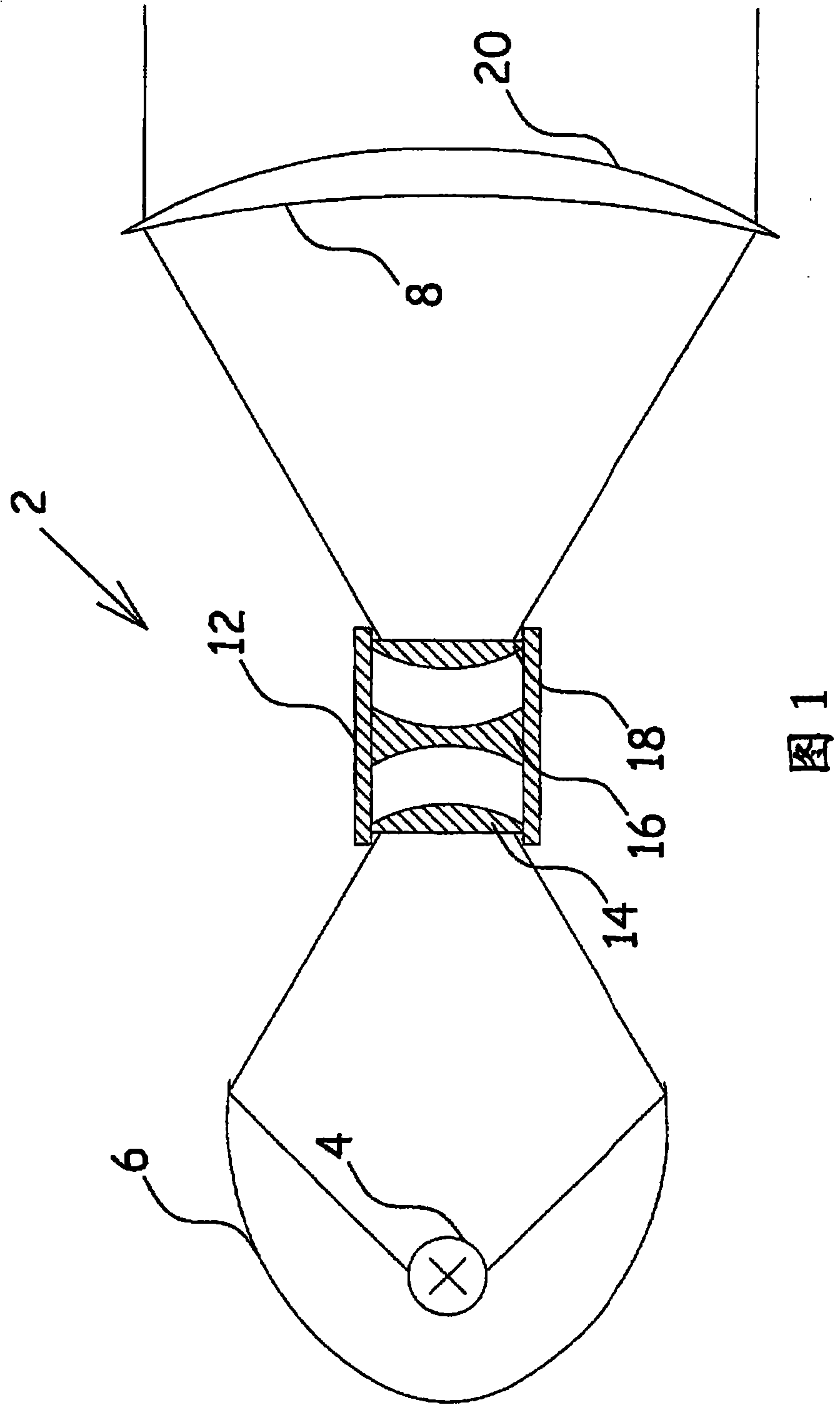
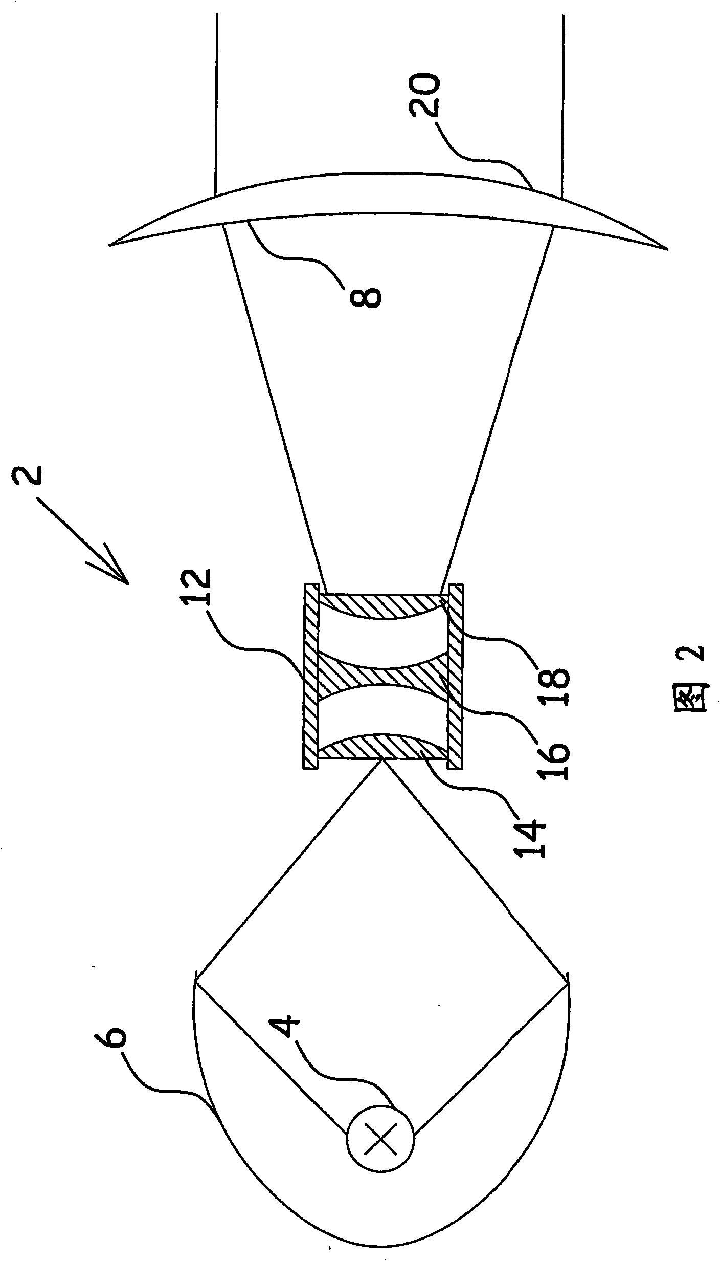
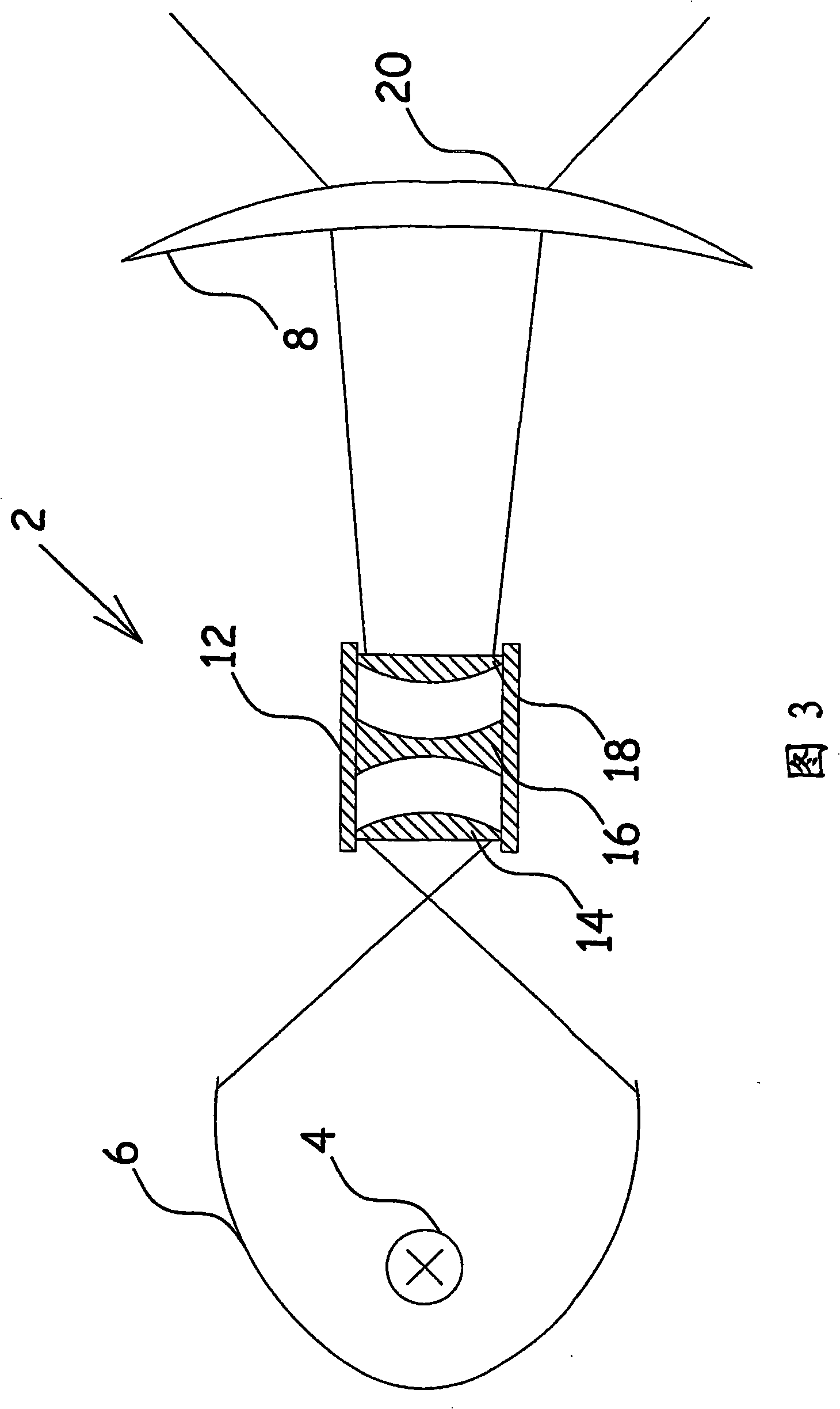
[0035]FIG. 1 shows an optical assembly 2 comprising a lamp 4 positioned relative to a reflector 6 . A front lens 8 is placed at the front end of the optical assembly 2 . Between the mirror 6 and the front lens 8 is placed a light deflecting device 12 comprising at least lenses 14 , 16 and 18 . The front lens 8 comprises a central region 20 which has different optical properties than the lens in the region surrounding the central region. In operation, the reflector 6 reflects the light emitted by the lamp 4 so that it is converged in the light deflecting means 12 . Before the light enters the light deflecting device, it may pass through a color changing device or an optical effect element. The light rays leaving the light deflecting means 12 diverge, causing substantially the entire backside of the front lens 8 to be illuminated. The front lens converges the light so that a relatively narrow beam leaves the optical assembly 2 .

[0036] FIG. 2 shows an optical assembly as s...


PUM


Abstract

The present invention relates to a method for forming a light beam, and to a light assembly comprising at least one light source placed in conjunction with a fixed reflector, which reflector forms a beam of light into light forming means, which light assembly comprises a front lens, where the light forming means at least comprise a light deflecting means for changing the light angle of the light beam after passing through the front lens. The object of the invention is to achieve a light assembly, where major optical components are mechanically fixed in relation to a housing for achieving a light assembly, the mass centre of which changes only slightly during operation. This can be achieved, if the front lens has a central part that differs from the surrounding parts of the front lens, and where the light deflecting means in a first position concentrates the light beam into the central part of the front lens to generate a wide-angle light beam, and where the light deflecting means in a second position distributes the light beam over the entire front lens to generate a narrow-angle light beam, because of the internal light deflecting means, the front lens does not have to be movable with respect to the housing.

Description

technical field [0001] The present invention relates to an optical assembly and a method comprising at least one light source generating a beam of light entering the light forming device and a light forming device comprising at least one device for changing the angle of light incident on a front lens and spatially distributed light deflection devices. Background technique [0002] US 6,808,969B2 relates to a first multi-lens array designed to have positive power lenses that generate multiple beams of convergent light rays, and a second multi-lens array designed to have negative power lenses that generate multiple beams of collimated light rays, in There is an optimal interval between the two multi-lens arrays. As the axial separation between the two multi-lens arrays increases, the divergence of the overall beam increases. A black gobo located around the lens reduces the effective optical effect by converting light into heat. [0003] US20050135106A1 relates to a Fresnel ...

Claims


Application Information

Patent Timeline
Patent Type & Authority Applications(China)
IPC IPC(8): F21S8/00F21V5/04F21V14/06F21W131/406
CPCF21V14/06F21V5/048F21W2131/406F21V5/008F21V5/02F21V13/04F21Y2101/00
Inventor D·T·约尔根森M·索伦森H·M·许尔达尔
Owner MARTIN PROFESSIONAL
Learn More