
Display quality testing apparatus and testing method

A detection device and display quality technology, which is applied in the direction of optical testing flaws/defects, optics, instruments, etc., can solve the problems of large human errors, high cost of halogen lamps, wrong judgments, etc., and achieve the effect of avoiding errors and improving detection accuracy

Inactive Publication Date: 2008-08-27
AU OPTRONICS CORP
View PDF1 Cites 36 Cited by
  • Summary
  • Abstract
  • Description
  • Claims
  • Application Information

AI Technical Summary

Problems solved by technology

This method of detecting whether the color of the panel surface is abnormal by human eyes to judge which layer of film quality or film thickness may be abnormal, and then judge whether the panel has water ripple defects, may bring large human errors, and even cause Lead to wrong judgments, and the use of halogen lamps is costly and energy-consuming
[0003] Chinese patent application number CN200610091230.9 discloses a display panel detection device, although the detection device uses a light emitting diode (LED) component as a detection light source, but the technical solution still requires visual inspection

Method used


Image

  • Display quality testing apparatus and testing method
  • Display quality testing apparatus and testing method
  • Display quality testing apparatus and testing method

Examples


Embodiment Construction

[0025] In order to make the above content of the present invention more comprehensible, a preferred embodiment will be described in detail below together with the accompanying drawings.

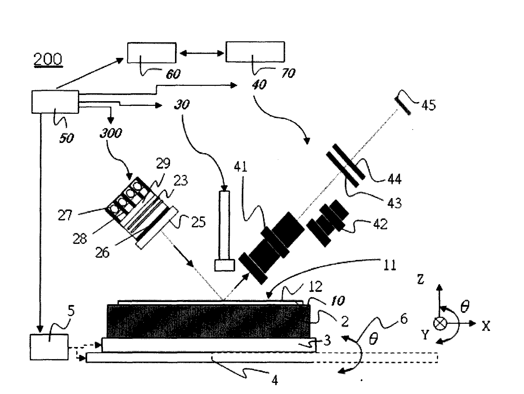
[0026] figure 2 middle,

[0027] 2 platforms

[0028] 3Y direction travel axis

[0029] 4X direction travel axis

[0030] 5X, Y, θ direction control motor

[0031] 6θ axis rotation direction

[0032] 10 substrates to be tested

[0033] 12 film surface

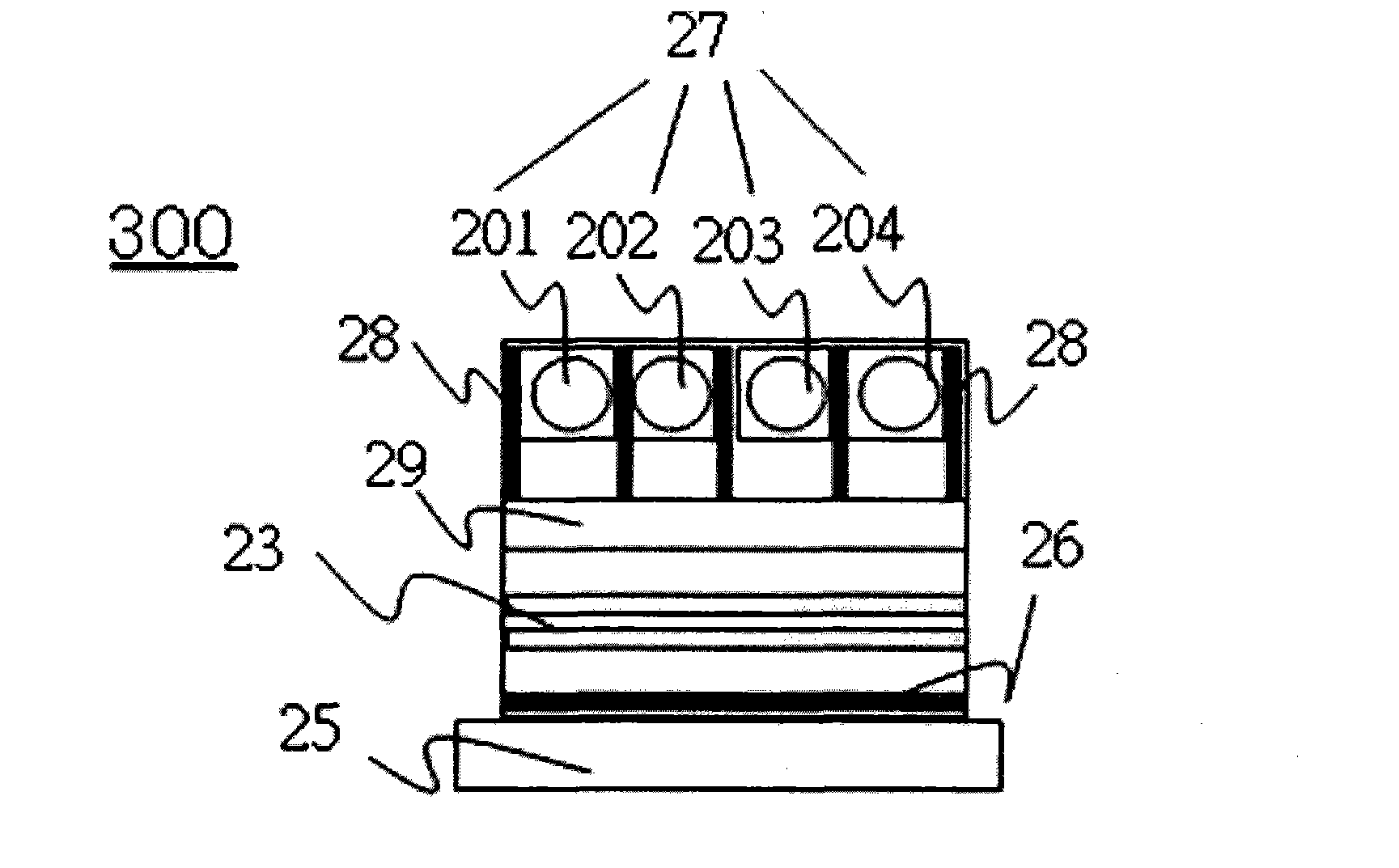
[0034] 23 Density Correction Filters

[0035] 25. Lens lens module

[0036] 26. Polarizer

[0037] 27 point light sources

[0038] 28. Point light source visor

[0039] 29 light mixing board

[0040] 30 microscopic device

[0041] 40 imaging unit

[0042] 41 lens lens

[0043] 42 lens lens

[0044] 43 Phase modulation compensator (Compensator)

[0045] 44 Analyzer (Analyer)

[0046] 45 sensors

[0047] 50 control device

[0048] 60 detection device

[0049] 70 data storage device

[0050] 200 display quality inspection de...


PUM


Abstract

The invention provides a detection device and a detection method for quality display. The detection device for quality display comprises a platform which is used for bearing a substrate, an image sampling unit, a control motor which is used for adjusting variation of the platform at different rotation angles and in different axial directions, a light mixing lens module which is used for generating a light mixing light source which is then outputted to the substrate for the image sampling unit to read image data from the substrate, a detection device which is used for judging the grey scale difference in the image data which is acquired by the image sampling unit, and a control device which is used for controlling the detection device, the control motor, the light mixing lens module and the image sampling unit. The detection device and the detection method for quality display can detect the defects of the substrate, improve the detection precision by utilization of the light mixing light source and the platform control motor, and avoid possible errors caused by eye judgment through conversion of images and grey scale signals into electrical signals and data processing in virtue of computer technologies.

Description

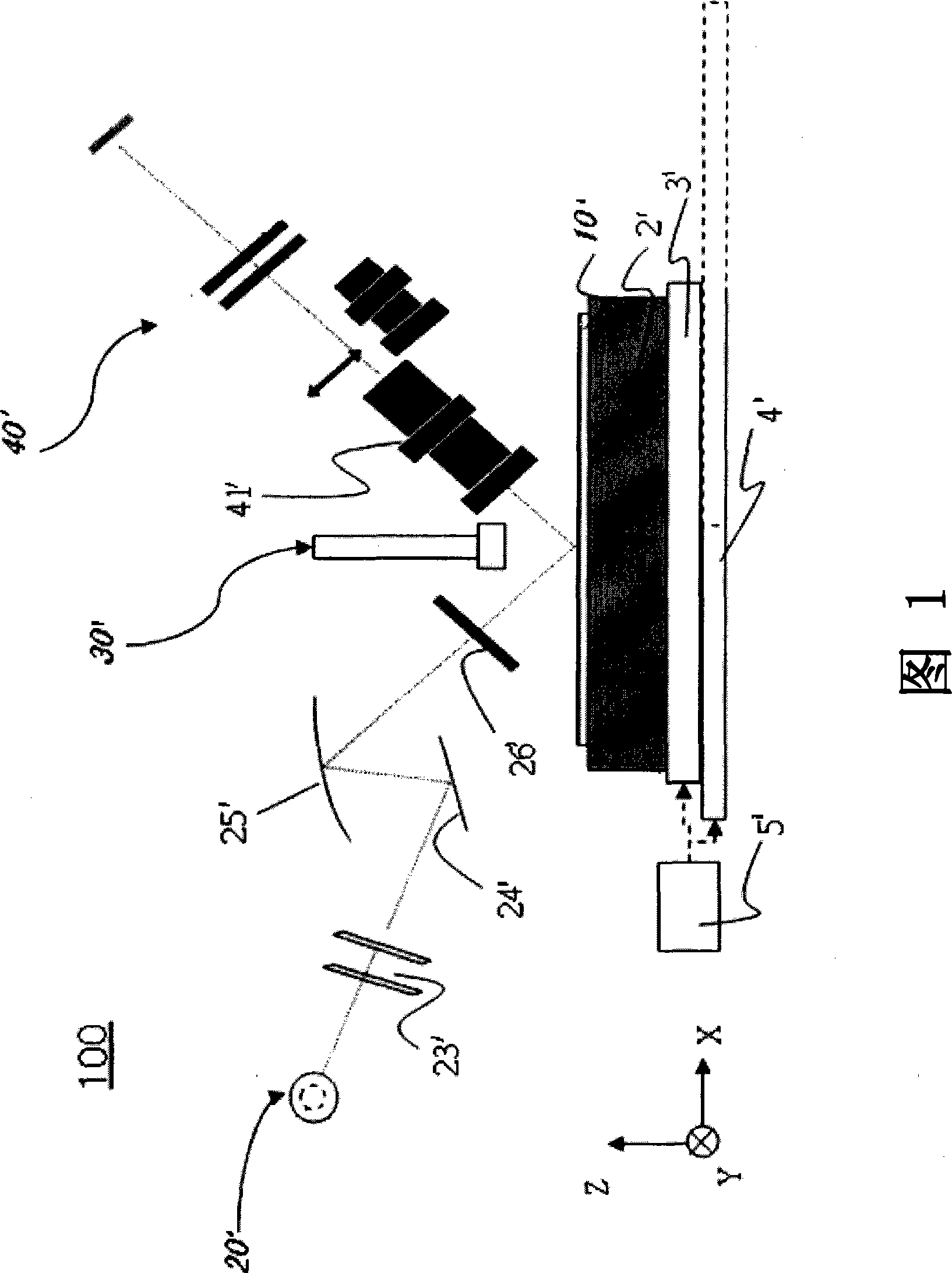
technical field [0001] The invention relates to a display quality detection device and a detection method, in particular to a display quality detection device and a detection method for defects of a display panel or a display substrate. Background technique [0002] At present, in the process of manufacturing the front-end thin film transistor array (Array) of a thin film transistor liquid crystal display (TFT-LCD), a halogen lamp is generally used. Referring to Fig. 1, the existing detection device 100 is after the light emitted by the halogen lamp 20' is processed by a density correction filter (ND filter) 23', a plane mirror 24', a reflecting mirror 25', and a polarizer 26', output to the substrate to be inspected 10' on the platform 2', and then the image data of the substrate to be inspected can be obtained from the microscopic device 30' and the photographic device 40' to analyze possible defects in the substrate to be inspected 10'. Defect: When the area of ​​the sub...

Claims


Application Information

Patent Timeline
IPC IPC(8): G02F1/13G01N21/95
Inventor 施宏伟
Owner AU OPTRONICS CORP
Learn More