
Injection type circulating fluid generator

A technology of circulating fluid and generator, applied in the direction of impact engine, hydropower, engine components, etc., can solve the problems of high investment cost and large energy consumption, and achieve the effects of no environmental pollution, low production cost and simple structure

Inactive Publication Date: 2008-08-27
黄智明
View PDF0 Cites 2 Cited by
  • Summary
  • Abstract
  • Description
  • Claims
  • Application Information

AI Technical Summary

Problems solved by technology

Thermal power generation consumes a lot of energy, hydropower and wind power generation require unique natural conditions, and the investment cost is high

Method used


Image

  • Injection type circulating fluid generator

Examples


Embodiment Construction

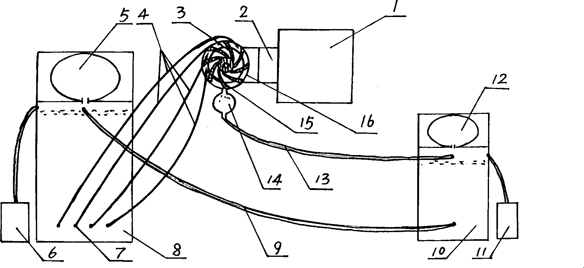
[0008] A jet-type circulating fluid generator, comprising a permanent magnet generator 1, a speed-regulating gear mechanism 2, a water wheel disc 16, a diversion tank 8, and a return tank 10, the water wheel disc 16 is provided with an impeller 3, and the water wheel disc 16 The output shaft is connected with the rotor of the permanent magnet generator 1 through the speed regulating gear mechanism 2, the upper ends of the diversion tank 8 and the return tank 10 are respectively provided with a pressure regulating air bag 5 and a pressure regulating air bag 12, and the inflators 6 and 11 are respectively connected with the diversion tank 8. The return tank 10 is connected. One end of the high-pressure water pipe 4 is connected to the water outlet valve 7 at the bottom of the diversion tank 8. The other end is installed with a nozzle 15. The direction of the nozzle 15 is facing the impeller 3 in the water wheel disc 16. The back flow pipe 9 The two ends are respectively connected...


PUM


Abstract

The invention provides a jet circulating fluid generator, comprising a magnetic generator, a speed regulation gear mechanism, a water rotary table, a stream guidance jar and a refluence jar, wherein, the inner part of the water rotary table is provided with an impeller, an output shaft of the water rotary table is connected with a rotor of the magnetic generator by the speed regulation gear mechanism, the upper ends of the stream guidance jar and the refluence jar are provided with a pressure adjusting air chamber, an inflator is connected with the stream guidance jar and the refluence jar, one end of a high pressure water pipe is connected with a water outlet valve on the lower part of the stream guidance jar, the other end of the high pressure water pipe is provided with a nozzle which is over against the impeller inside the water rotary table, the two ends of a refluence water pipe are respectively switched in the stream guidance jar and the refluence jar, the water rotary table is communicated with a cushioning ball which is switched in the refluence jar through a cushion water pipe. The jet circulating fluid generator of the invention has simple structure, low production cost and no environment pollution; the jet circulating fluid generator has the characteristics of energy and water saving, safety and convenient maintenance, etc., thereby being suitable for the disperse building and use, especially for the peasant household in remote and mountain areas and pastoral areas.

Description

technical field [0001] The invention relates to a generator, in particular to a jet-type circulating fluid generator. Background technique [0002] Natural resources are limited, and the world's energy shortage is obvious to all. Thermal power generation consumes a large amount of energy, while hydropower and wind power generation require unique natural conditions and high investment costs. Contents of the invention [0003] The object of the present invention is to provide a jet-type circulating fluid generator with simple structure, low production cost, energy saving and no environmental pollution. [0004] The jet-type circulating fluid generator of the present invention includes a permanent magnet generator, a speed-regulating gear mechanism, a water wheel disc, a diversion tank, and a return tank. The water wheel disc is provided with an impeller, and the output shaft of the water wheel disc passes through the speed-regulating gear The mechanism is connected with th...

Claims


Application Information

Patent Timeline
Patent Type & Authority Applications(China)
IPC IPC(8): F03B1/00F03B13/00
CPCY02B10/50Y02E10/223Y02E10/20
Inventor 黄智明
Owner 黄智明
Learn More