
Driving apparatus

A technology of driving device and driven body, applied in the direction of installation, generator/motor, piezoelectric effect/electrostrictive or magnetostrictive motor, etc., can solve the problem of inability to ensure impact resistance, displacement suppression unit collision, Problems such as destroying piezoelectric elements

Inactive Publication Date: 2008-08-20
SHARP KK
View PDF2 Cites 3 Cited by
  • Summary
  • Abstract
  • Description
  • Claims
  • Application Information

AI Technical Summary

Problems solved by technology

In such a structure, sufficient impact resistance cannot be ensured
[0006] In addition, as described in Patent Document 2, in the structure provided with a displacement suppression unit for suppressing the displacement of the holder, the displacement suppression unit collides with the piezoelectric element.
Due to this collision, it is possible to destroy the more brittle piezoelectric element

Method used


Image

  • Driving apparatus
  • Driving apparatus
  • Driving apparatus

Examples


Embodiment Construction

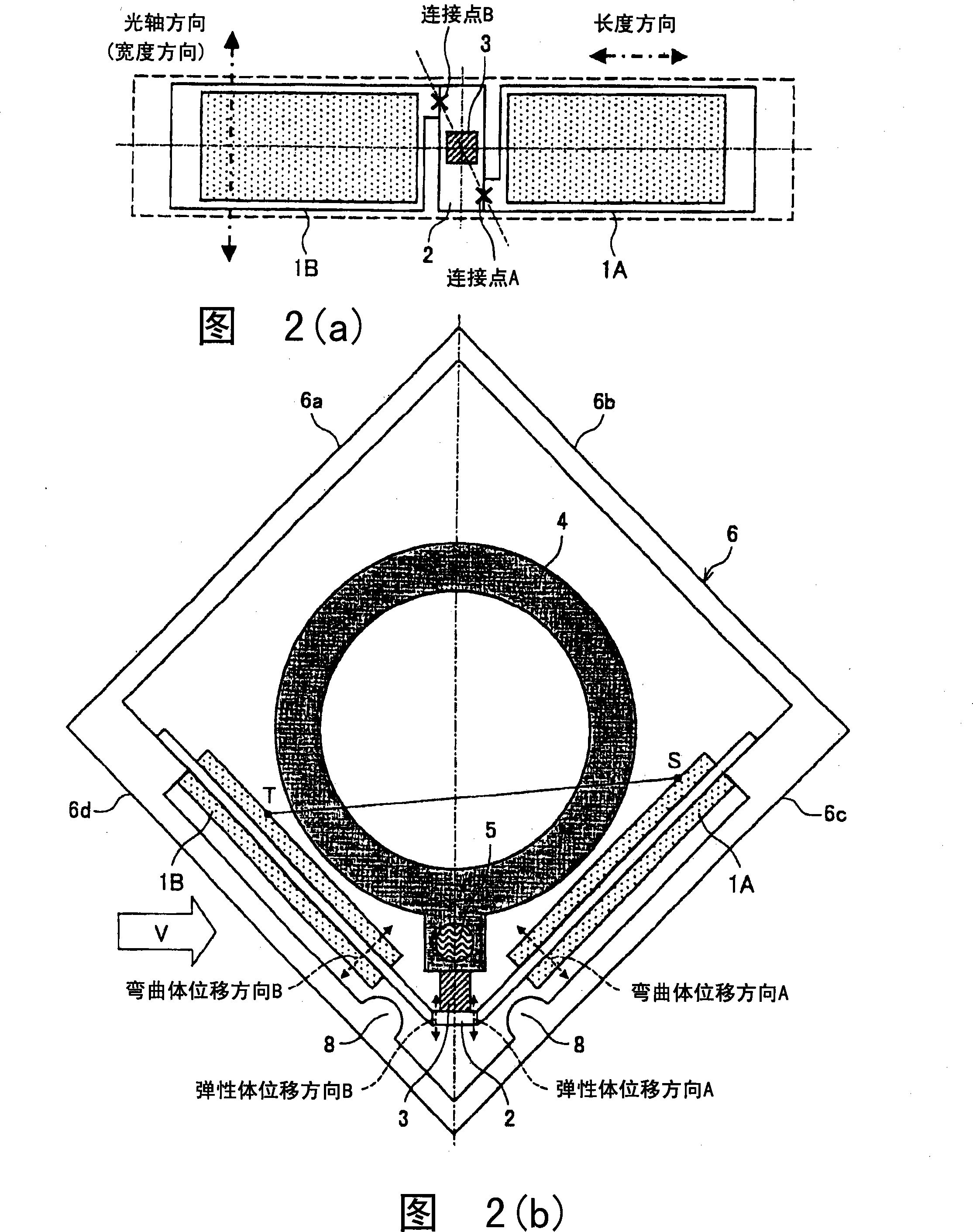
[0027] The driving device of the present invention includes: a bending displacement member; and a control unit for electrically controlling the bending displacement of the bending displacement member. That is, in the drive device, the bending displacement of the bending displacement member can be excited by electrical control by the control unit. First, a bending displacement member that excites bending displacement by electrical control will be described. As an example of the bending displacement member, a piezoelectric element having a bimorph structure as shown in FIGS. 5( a ) and 5 ( b ) is mentioned.

[0028] FIG. 5( a ) is a side view showing the structure of a piezoelectric element having a bimorph structure, and FIG. 5( b ) is a diagram showing a state of bending displacement of the piezoelectric element.

[0029] The piezoelectric element shown in FIG. 5(a) and FIG. 5(b) has: two piezoelectric material layers 22X·22Y, and a spacer (vibration plate) 21 made of metal, ...


PUM


Abstract

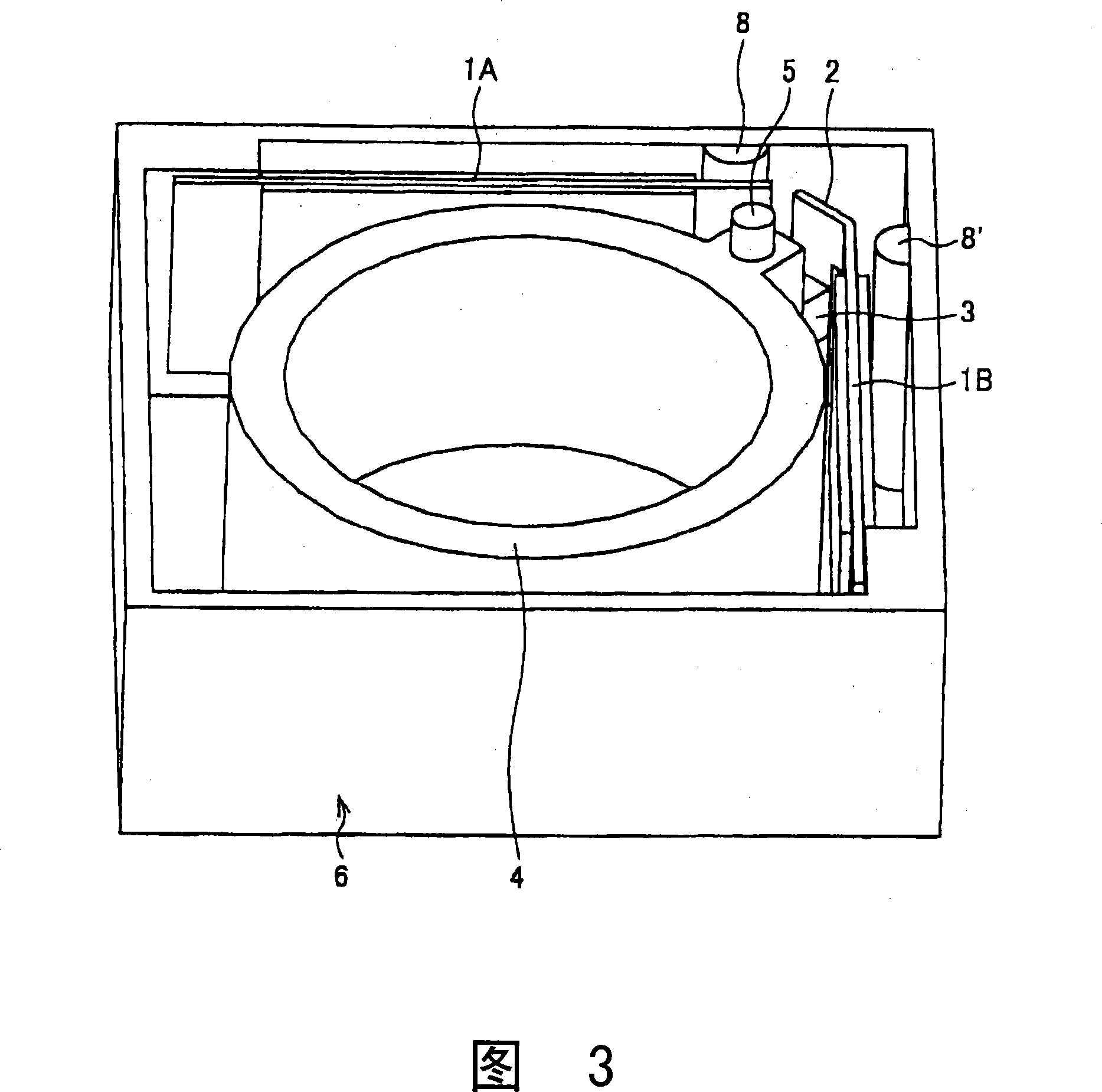
To realize a driving apparatus where vibrational movement of a piezoelectric element is ensured; sufficient impact resistance is provided; and damages to the piezoelectric element is prevented, a driving apparatus of the present invention has: a flex movement member 1A or 1B for serving as a driving source to drive a lens barrel 4, the flex movement member including: a piezoelectric member 22X or 22Y which extends and contracts under electric control; and a shim 21 larger than the piezoelectric member 22X or 22Y, the piezoelectric member and the vibrational plate attached to each other; and protruding sections 8 for restricting an excessive flex movement of the shim 21 of the flex movement member 1A or 1B, the protruding sections 8 being at a position where the protruding sections 8 will not contact with the piezoelectric member 1A or 1B of the flex movement member 22X or 22Y when the flex movement member is making an excessive flex movement beyond a maximum flex movement amount, where the maximum flex movement amount is greatest among flex movement amounts necessary for the flex movement member 1A or 1B to drive the lens barrel 4. This provides the driving apparatus with enough impact resistance, and prevents damage to the piezoelectric element.

Description

technical field [0001] The present invention relates to a driving device having a driving mechanism for driving a driven body. Background technique [0002] In the past, a driving device having a driving mechanism for driving a driven body using vibration of a piezoelectric element has been developed. In this driving device, the piezoelectric element is vibrated by repeatedly applying a voltage to the piezoelectric element. Generally, since piezoelectric elements are made of relatively brittle materials such as ceramics, there is a problem that they are easily damaged due to deformation caused by drops and impacts. In response to this problem, for example, in Patent Document 1 (Japanese Unexamined Patent Publication No. 2004-254417 (published on September 9, 2004)), a piezoelectric device in which piezoelectric elements are bonded to both sides of a reinforcing plate made of stainless steel or the like is proposed. Actuator. [0003] In addition, not limited to actuators ...

Claims


Application Information

Patent Timeline
Patent Type & Authority Applications(China)
IPC IPC(8): H02N2/00G02B7/04H10N30/20
CPCH02N2/026G02B7/08H01L41/0946H10N30/2043
Inventor 西冈澄人
Owner SHARP KK
Learn More