
Driving method and driving apparatus of liquid crystal display

A technology of liquid crystal display and driving method, which is applied in the field of driving of liquid crystal display and its driving device, and can solve problems such as function decline

Inactive Publication Date: 2008-08-20
SAMSUNG ELECTRONICS CO LTD
View PDF0 Cites 13 Cited by
  • Summary
  • Abstract
  • Description
  • Claims
  • Application Information

AI Technical Summary

Problems solved by technology

Therefore, in bright daylight, the role of outdoor LCD will likely be reduced

Method used


Image

  • Driving method and driving apparatus of liquid crystal display
  • Driving method and driving apparatus of liquid crystal display
  • Driving method and driving apparatus of liquid crystal display

Examples


Embodiment Construction

[0031] Hereinafter, exemplary embodiments of the present invention will be described in detail with reference to the accompanying drawings. In the drawings, the thickness of layers, films, panels, and regions are exaggerated for clarity. Like numbers may indicate like or similar elements throughout the description of the figures. It will be understood that when an element such as a layer, film, region, substrate, or panel is referred to as being "on" another element, it can be directly on the other element or intervening elements may also be present.

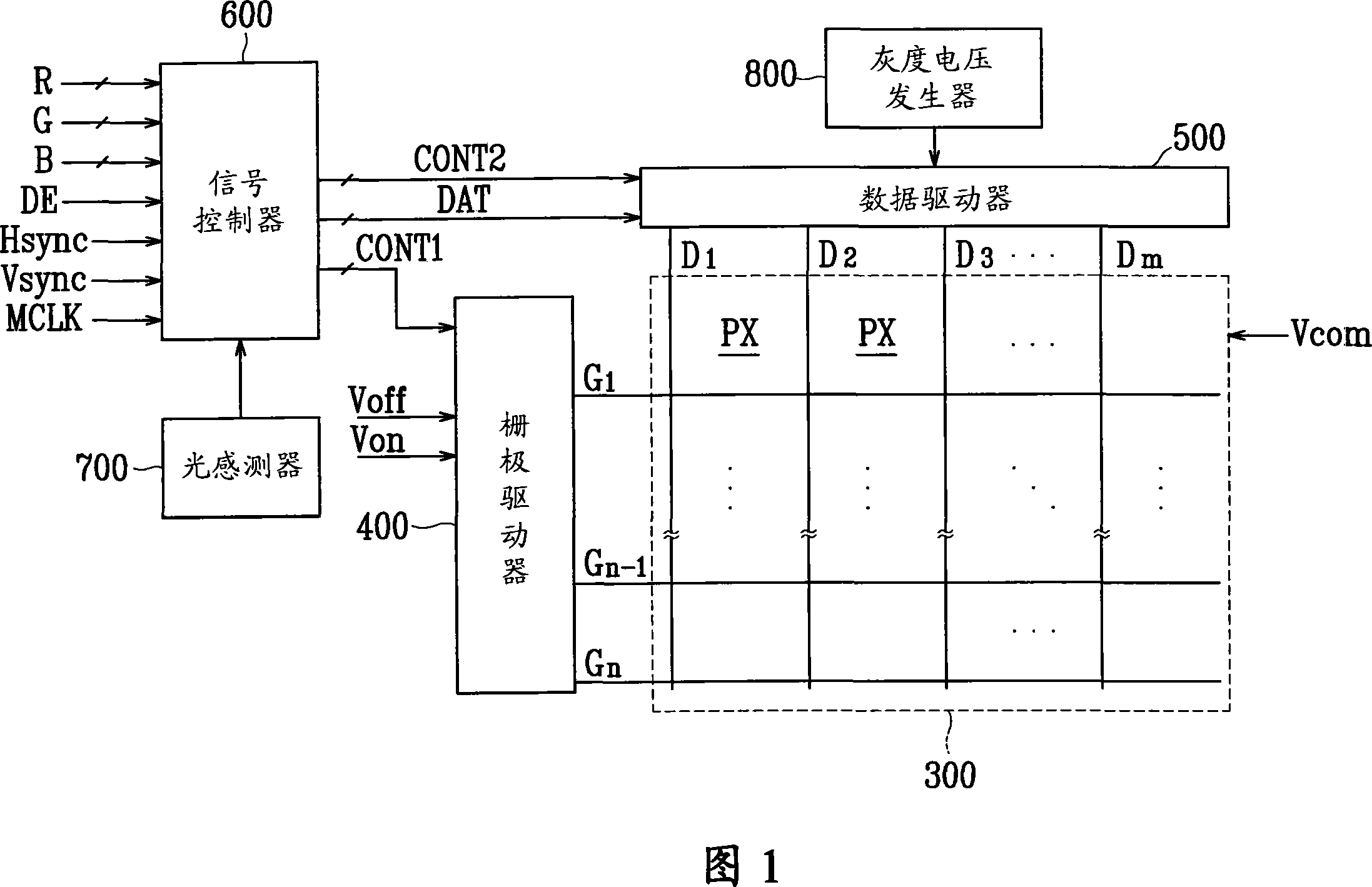
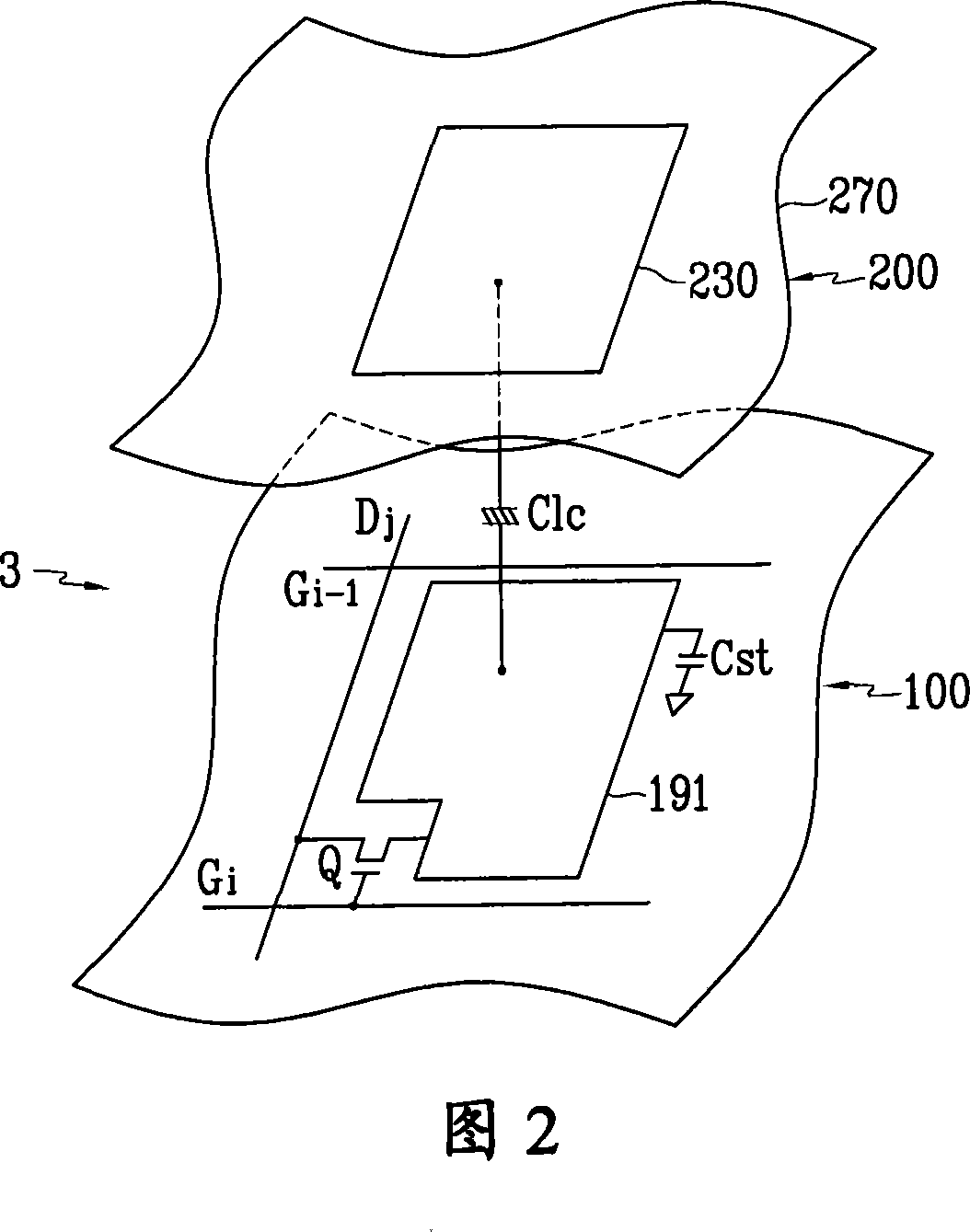
[0032] First, an LCD according to an exemplary embodiment of the present invention will be described in detail below with reference to FIGS. 1 and 2 .

[0033] FIG. 1 is a block diagram illustrating an LCD according to an exemplary embodiment of the present invention. FIG. 2 is an equivalent circuit diagram of a pixel of the LCD shown in FIG. 1 according to an exemplary embodiment of the present invention.

[0034] Referring ...


PUM


Abstract

A driving method includes sensing illuminance of ambient light, determining a first contrast ratio based on the sensed illuminance, determining a second contrast ratio and a relative ratio of the contrast ratio, determining a gradient of a compensation gamma curve using the relative ratio, determining an average gray of input data signals, and determining the compensation gamma curve.

Description

technical field [0001] The invention relates to a driving method and a driving device of a liquid crystal display. Background technique [0002] A liquid crystal display (LCD) includes two panels having field generating electrodes (eg, a pixel electrode and a common electrode) and a liquid crystal layer having dielectric anisotropy therebetween. The LCD also includes switching devices, such as thin film transistors (TFTs), connected to the pixel electrodes, and a plurality of signal lines, such as gate lines and data lines, to control the switching devices to apply voltages to the pixel electrodes. A common voltage is applied to a common electrode that may be formed over the entire surface of one of the two panels. The pixel electrode, the common electrode, and the intervening liquid crystal layer together constitute a liquid crystal capacitor. [0003] A liquid crystal capacitor and a switching element connected to the liquid crystal capacitor form an individual unit cell...

Claims


Application Information

Patent Timeline
Patent Type & Authority Applications(China)
IPC IPC(8): G09G3/36G09G5/02
CPCG09G2360/16G09G2320/066G09G3/36G09G2320/0673G09G2320/0271G09G2360/144G09G3/3648G01J1/40G09G3/20H04N5/202
Inventor 李起赞朴东园
Owner SAMSUNG ELECTRONICS CO LTD
Learn More