


Quick Research
Generate reliable direction feasibility study reports for your R&D in just a few steps.

Technical Q&A
Discover and master advanced knowledge NOW. Basics, ideas, possibilities, all at once.

Find Solutions
As an expert in R&D theories, this can generate solutions to your technical problems instantly.

Evaluate Feasibility
Analyze your overall solution with one click, know your potential R&D risks in advance.

Monitor Landscape
Get weekly tech updates, stay abreast of the latest tech innovations and key insights.
Thin wire locking method and device thereof
A locking device and filament technology, applied in the direction of transmission elements or pulley ropes or cables, textile cables, belts/chains/gears, etc., can solve the problems of small locking force, easy sliding and misalignment, etc., to achieve lock Large tightening force, easy processing and production, and simple design and structure
- Summary
- Abstract
- Description
- Claims
- Application Information
AI Technical Summary
Problems solved by technology
Method used
Image


Examples
no. 1 Embodiment
[0048] figure 1 Indicates the general assembly structure of the locking device. The locking device is composed of a fixing bolt 101 , a clamping sleeve 102 and a locking cap 103 . The clamping sleeve 102 has a tapered structure and is located inside the locking cap 103; the locking cap 103 is located at the upper end of the fixing bolt 101, and the two are locked with each other through internal and external threads; the locked filament 104 runs through the entire locking device along the central axis.
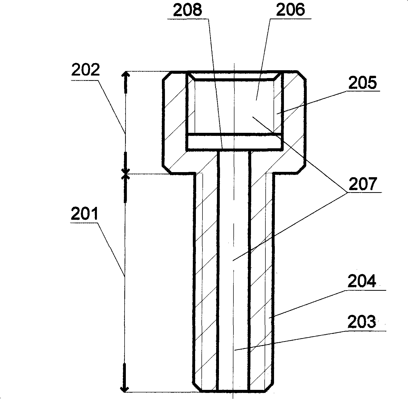
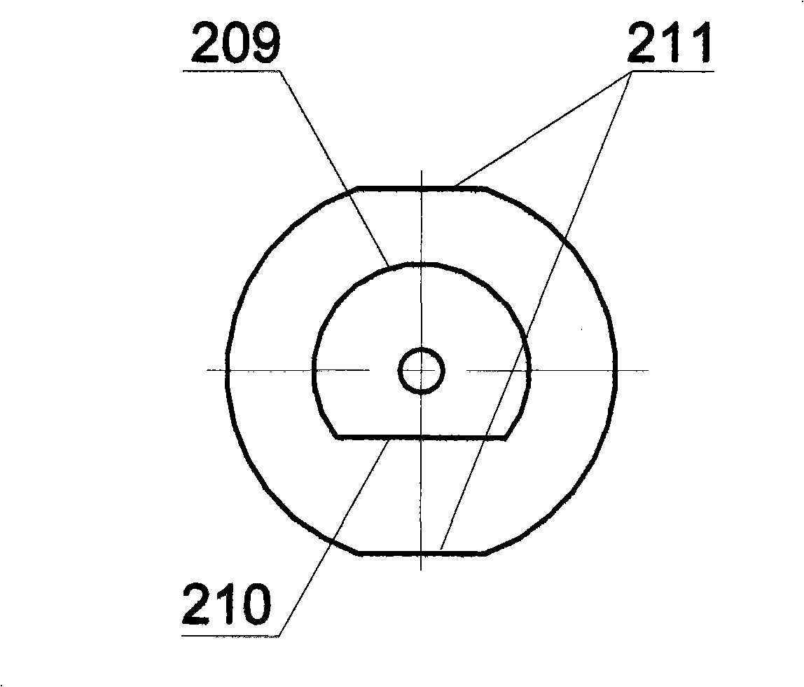
[0049] FIG. 2( a ) shows the internal structure of the fixing bolt 101 . The fixing bolt 101 mainly includes two parts: a bolt shaft 201 and a bolt cap 202 , wherein the bolt shaft 201 includes a lower through hole 203 inside, the lower through hole is a circular through hole, and the lower through hole runs through the entire bolt shaft 201 .
[0050] The length of the bolt cap 202 is slightly longer than the bolt shaft 302 of the locking cap 103 . Bolt cap 202 inside comp...
no. 2 Embodiment
[0066] On the basis of the first embodiment, by increasing the number of thread clamping holes and rectangular grooves of the clamping sleeve, two non-adjacent filaments or three non-adjacent filaments can be locked at the same time.
[0067] Figure 5(a) shows the internal structure of the clamping sleeve for clamping two non-adjacent filaments. The clamping sleeve 501 is in the shape of a truncated cone, and its material is spring steel. The filament clamping holes 504 are symmetrically located on both sides of the center of the clamping sleeve 501, and the filament clamping holes 504 are two circular through holes with equal diameters, and the two circular through holes pass through the entire clamping sleeve 501. And vertically penetrate the lower bottom surface 502 and the upper bottom surface 503 , the two circular through holes are separated from each other by a certain distance.
[0068] Figure 5(b) shows a top view of the clamping sleeve used to clamp two non-adjacent...
no. 3 Embodiment
[0079] On the basis of the first embodiment, by increasing the number of thread clamping holes and rectangular slots of the clamping sleeve, two filaments with tangential outer diameters or three filaments with tangential outer diameters can be locked at the same time.
[0080] Figure 7(a) shows the internal structure of the clamping sleeve used to clamp two filaments with tangential outer diameters. The clamping sleeve 701 is in the shape of a truncated cone, and its material is spring steel. The filament clamping hole 704 is two circular through holes with tangential outer diameters, the two circular through holes are tangent to the central axis of the clamping sleeve 701, and the diameters of the two circular through holes are the same, so The above two circular through holes both vertically penetrate the lower bottom surface 702 and the upper bottom surface 703 .
[0081] Fig. 7(b) shows a sectional view of a clamping sleeve for clamping two filaments with tangential oute...
PUM
 Abstract
Description
Claims
Application Information
 - R&D Engineer
- R&D Manager
- IP Professional
- Industry Leading Data Capabilities
- Powerful AI technology
- Patent DNA Extraction
Browse by: Latest US Patents, China's latest patents, Technical Efficacy Thesaurus, Application Domain, Technology Topic, Popular Technical Reports.
© 2024 PatSnap. All rights reserved.Legal|Privacy policy|Modern Slavery Act Transparency Statement|Sitemap|About US| Contact US: help@patsnap.com