
Radiator for vehicle

A radiator and radiator fan technology, which is applied to vehicle components, machines/engines, engine cooling, etc., can solve the problems of increased weight, complex contour structure, and reduced design freedom of contour structure, etc. The effect of large opening area and simplified assembly work

Active Publication Date: 2008-08-13
HONDA MOTOR CO LTD
View PDF2 Cites 4 Cited by
  • Summary
  • Abstract
  • Description
  • Claims
  • Application Information

AI Technical Summary

Problems solved by technology

Therefore, the weight of the cover is increased by increasing the thickness of the cover
[0008] In addition, there is also a problem that since one end face of the cover has a profile connected to the radiator and the other end face has a profile connected to the crankcase, the profile structure of the cover is very complicated, while reducing the profile structure design. degrees of freedom

Method used


Image

  • Radiator for vehicle
  • Radiator for vehicle
  • Radiator for vehicle

Examples


Embodiment Construction

[0047] Referring to Figures 1-9, an embodiment of the present invention is described below.

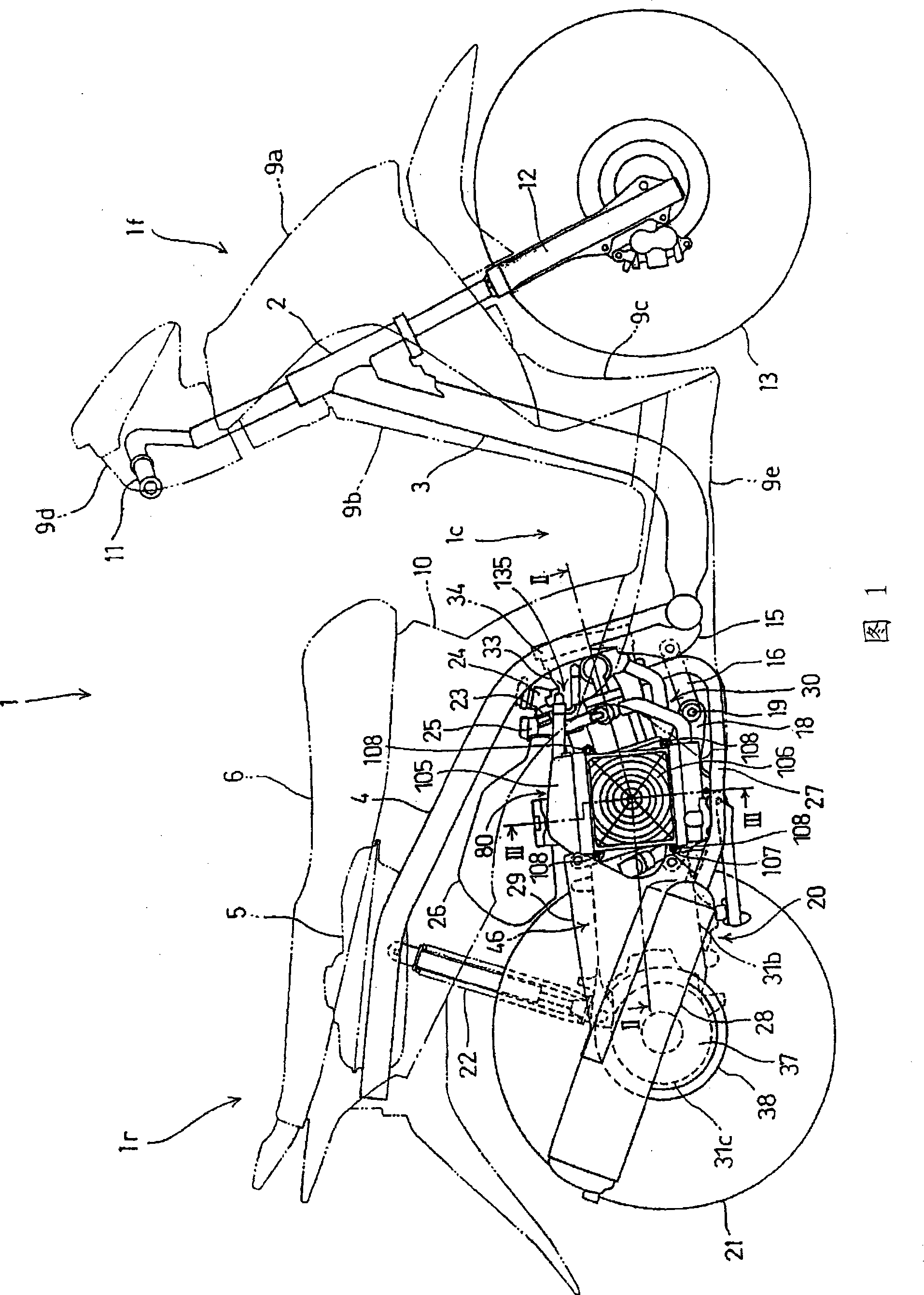
[0048] FIG. 1 is a side view showing a scooter 1 corresponding to one embodiment of the present invention.

[0049] In this embodiment, its position is described in terms of the vehicle's forward state.

[0050] The front part 1f of the vehicle body and the rear part 1r of the vehicle body are connected through the low floor 1c and the vehicle frame.

[0051] Specifically, the frame lower tongue 3 extends downward from the head pipe 2 in the vehicle body front portion 1f, the frame lower tongue 3 is bent horizontally downstream and extends rearward under the bottom plate 1c, and a pair of right and left main pipes 4 are coupled to At the rear end of the lower tongue of the vehicle frame, the main pipe 4 rises diagonally rearwardly from its coupling portion, bends horizontally at a predetermined height, and extends rearwardly.

[0052] Fuel tank 5 and other parts all are supported by...


PUM


Abstract

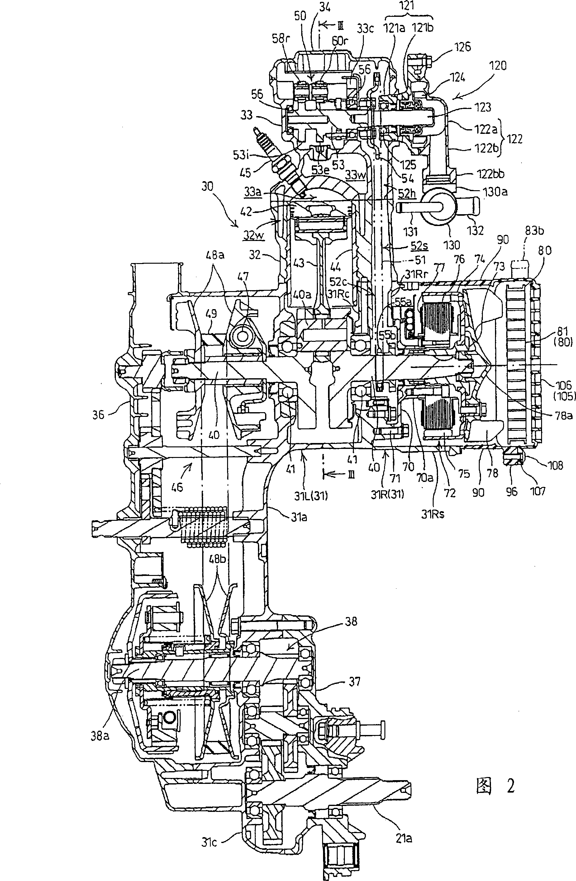
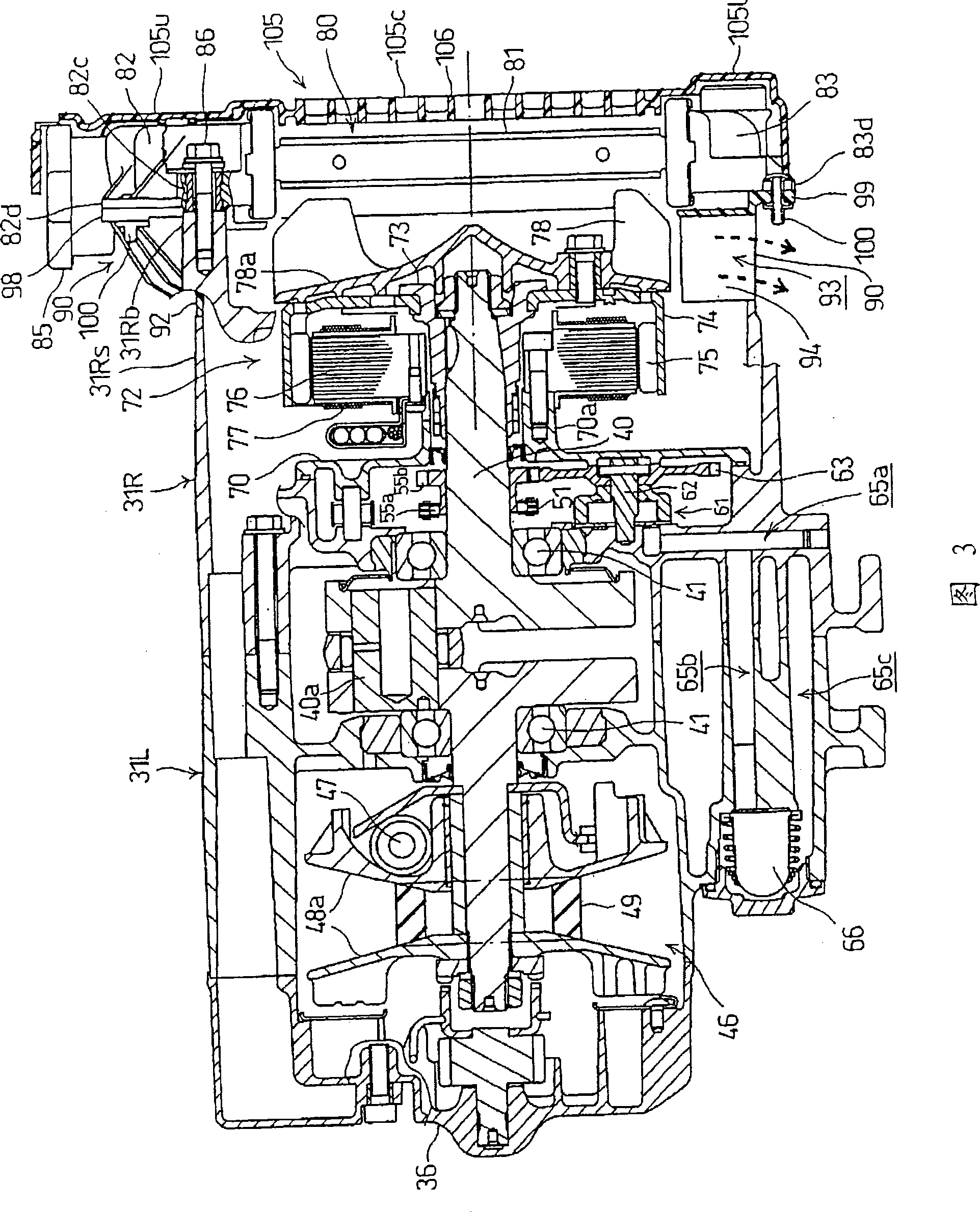
The invention discloses a vehicle radiator, which is located at one side of the crankcase of a water-cooled internal combustion engine and is directly fixed on the crankcase. Between the vehicle radiator and the crankcase, there is a cover provided with an exhaust port for cooling air flowing through the radiator. The cooling water channel structure of the water-cooled internal combustion engine is provided with a bypass branch pipe and an intake branch pipe branched from the main pipe of the branch connection pipe. The branch connection pipe protrudes from the cylinder head, and a connecting part of the main pipe is directly connected to the cylinder head The other connecting part of the water tank is connected with the radiator through the radiator inlet pipe, the bypass branch pipe is connected with the temperature regulating device, and the intake branch pipe is connected with the water pump.

Description

technical field [0001] The invention relates to a vehicle radiator for a water-cooled internal combustion engine and a water-cooling channel structure for a water-cooled combustion engine. Background technique [0002] One known radiator is fixed to a water-cooled internal combustion engine by means of a cover separate from the radiator. The radiator fan is mounted on the back of the radiator together with a shroud having an exhaust passage surrounding the periphery of the radiator fan inserted between the internal combustion engine and the radiator. See, for example, Japanese Patent No. 3696508. [0003] In Japanese Patent No. 3696508, the radiator is placed to the right of the internal combustion engine, which is located in front of the oscillating power pack on the motorcycle. [0004] The AC generator is provided at the right end protruding rightward from the right crankcase of the crankshaft positioned horizontally in the transverse direction of the internal combustio...

Claims


Application Information

Patent Timeline
Patent Type & Authority Applications(China)
IPC IPC(8): F01P3/18B60K11/04
Inventor 平山周二山西辉英
Owner HONDA MOTOR CO LTD
Learn More