Method for correcting laser carving machine mechanism relative position

A laser engraving machine, relative position technology, applied in engraving, laser welding equipment, decorative art, etc., can solve the problems of mechanism work difference, vibration, shaking, cumbersome procedures, etc.

Active Publication Date: 2012-07-04
XINGYUN COMP
View PDF0 Cites 0 Cited by
  • Summary
  • Abstract
  • Description
  • Claims
  • Application Information

AI Technical Summary

Problems solved by technology

[0003] In the structural design of today's laser engraving machines, the laser output device and the camera sensor device (CCD) are combined on the same frame, so that the output device and the camera sensor device can form a relative synchronous displacement. However, before the engraving process , due to the problem of poor workmanship in the assembly of the mechanism, plus the vibration and shaking during transportation or use, the output device and the camera sensing device must be adjusted to improve the accuracy of the output device when cutting
The usual method is to use the printer to print out a reference point, and then observe the actual cutting error to fill in the correction value and send it to the computer for correction. However, the manual correction procedure is cumbersome, and the cutting accuracy of the output device after correction is not high. accurate as expected

Method used


Image

  • Method for correcting laser carving machine mechanism relative position
  • Method for correcting laser carving machine mechanism relative position

Examples


Embodiment Construction

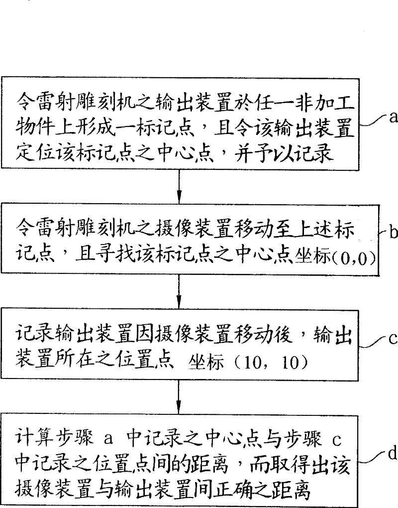
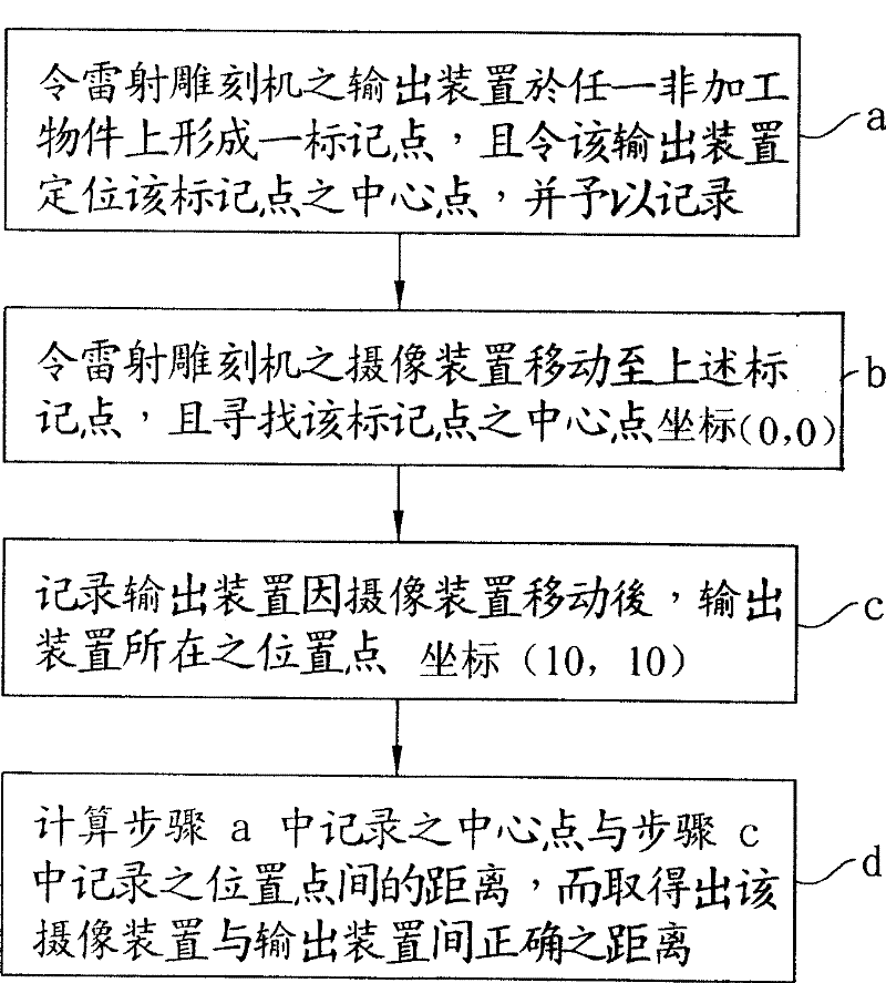
[0013] see figure 1 , the content of the accompanying drawing is a flow chart of an embodiment of the method for correcting the relative position of the mechanism in the laser engraving machine according to the present invention, which includes the following steps:

[0014] a. Let the output device of the laser engraving machine form a marking point on any non-processing object, and make the output device locate the center point of the marking point and record it;

[0015] b. Make the camera sensor device (CCD) of the laser engraving machine move to the above-mentioned marking point, and find the center point of the marking point;

[0016] c. Record the position of the output device after the camera sensor device moves; and

[0017] d. Calculate the distance between the center point recorded in step a and the position point recorded in step c, so as to obtain the correct distance between the camera sensing device and the output device.

[0018] Among them, the recording and ...


PUM


Abstract

The invention relates to a method of regulating an institution relative position in a laser engraving machine, mainly comprising: making an output device of the laser engraving machine form a marking point in any one of non-manufacturing objects; arranging and recording the output device in the centre of the marking point; moving a videography sensing device (CCD) of the laser engraving machine to the marking point and searching for the centre of the marking point; recording the position point of the output device after moving the videography sensing device; finally calculating a distance between the recorded centre of the output device and the position point after moving the output device, so as to obtain a correct distance between the videography sensing device and the output device.

Description

technical field [0001] The invention relates to a method for correcting the relative position of a mechanism in a laser engraving machine, in particular to a method for utilizing the dependency of the structure position setting between the camera sensor device (CCD) and the output device of the laser engraving machine, through the camera sensor The displacement relationship and positioning relationship between the device and the output device, and effectively and accurately obtain the distance between the two to correct the mechanism error of the camera sensing device and the output device in the laser engraving machine, which is suitable for the laser engraving machine before leaving the factory Calibration, or application before engraving for the first time on the user side. Background technique [0002] The process of using laser engraving is very simple, just like using a computer and printer to print on paper, as long as the various patterns are edited, the pattern can ...

Claims


Application Information

Patent Timeline
Patent Type & Authority Patents(China)
IPC IPC(8): B44B3/00B44B3/06B41M5/24B44B1/00B23K26/08B23K26/02B23K26/70
Inventor 郭信贤陈宗义苏尊尧
Owner XINGYUN COMP
Why Eureka
Try Eureka