
Method for automatic generation of network element deployment parameters

An automatic generation and parameter technology, applied in electrical components, digital transmission systems, data exchange networks, etc., to solve problems such as network element deployment, end-to-end business cannot be transferred accurately and effectively, etc.

Active Publication Date: 2008-08-06
CHINA MOBILE COMM GRP CO LTD
View PDF0 Cites 19 Cited by
  • Summary
  • Abstract
  • Description
  • Claims
  • Application Information

AI Technical Summary

Problems solved by technology

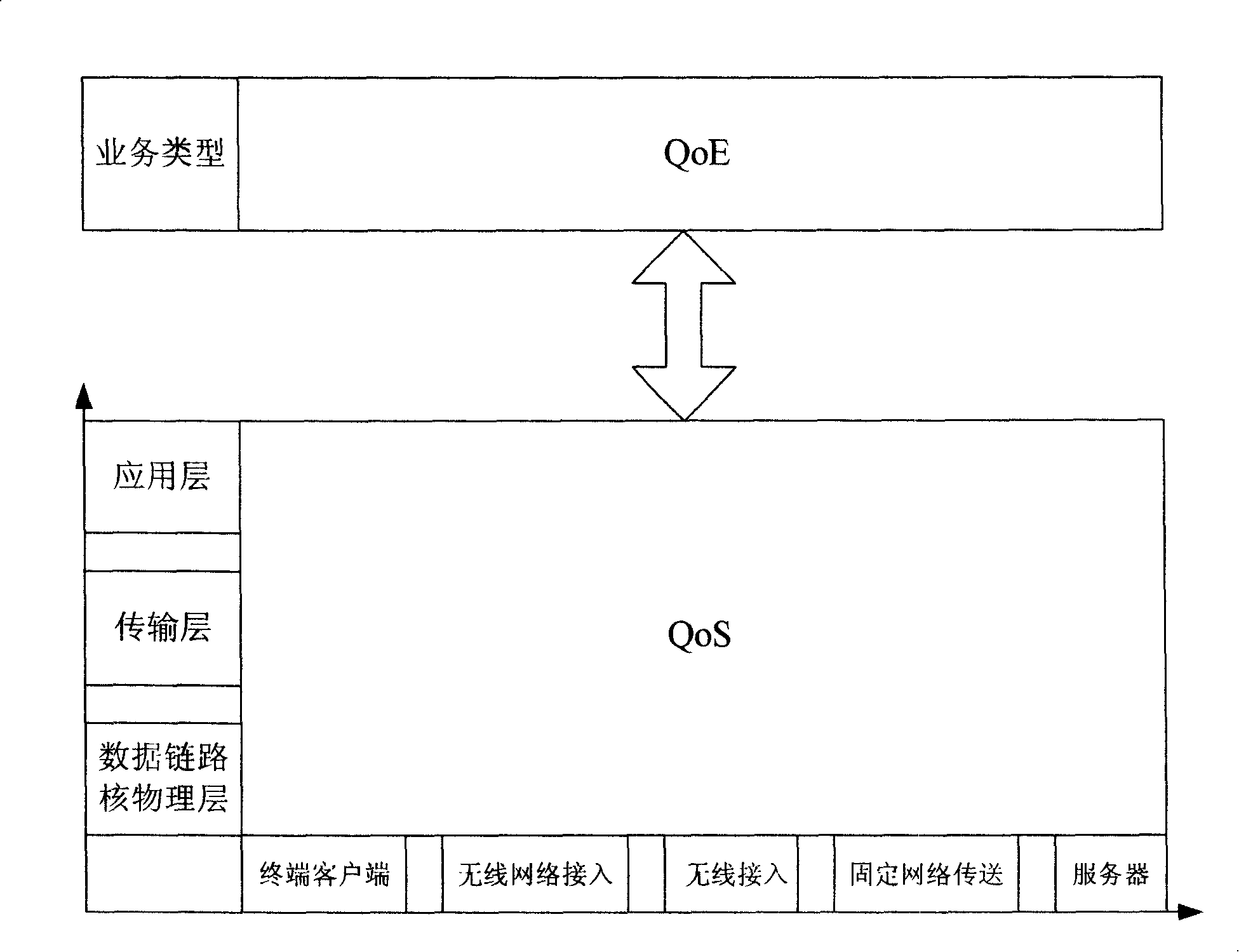
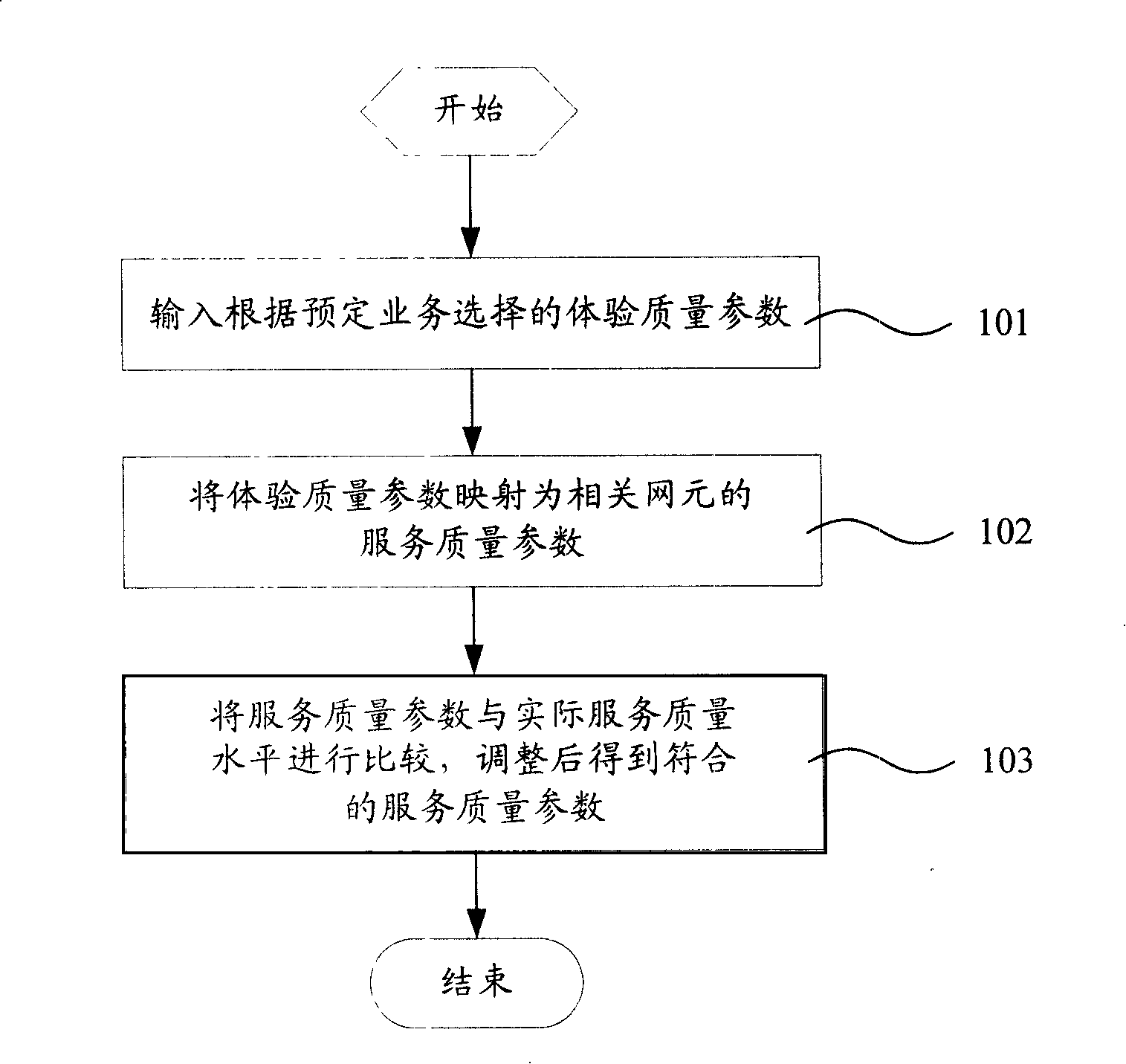
[0004] The purpose of the present invention is to propose a method for automatically generating network element deployment parameters based on the problem that the existing evaluation system for end-to-end services cannot be effectively deployed. QoE) to select the appropriate network element deployment scheme

Method used


Image

  • Method for automatic generation of network element deployment parameters
  • Method for automatic generation of network element deployment parameters
  • Method for automatic generation of network element deployment parameters

Examples


Embodiment Construction

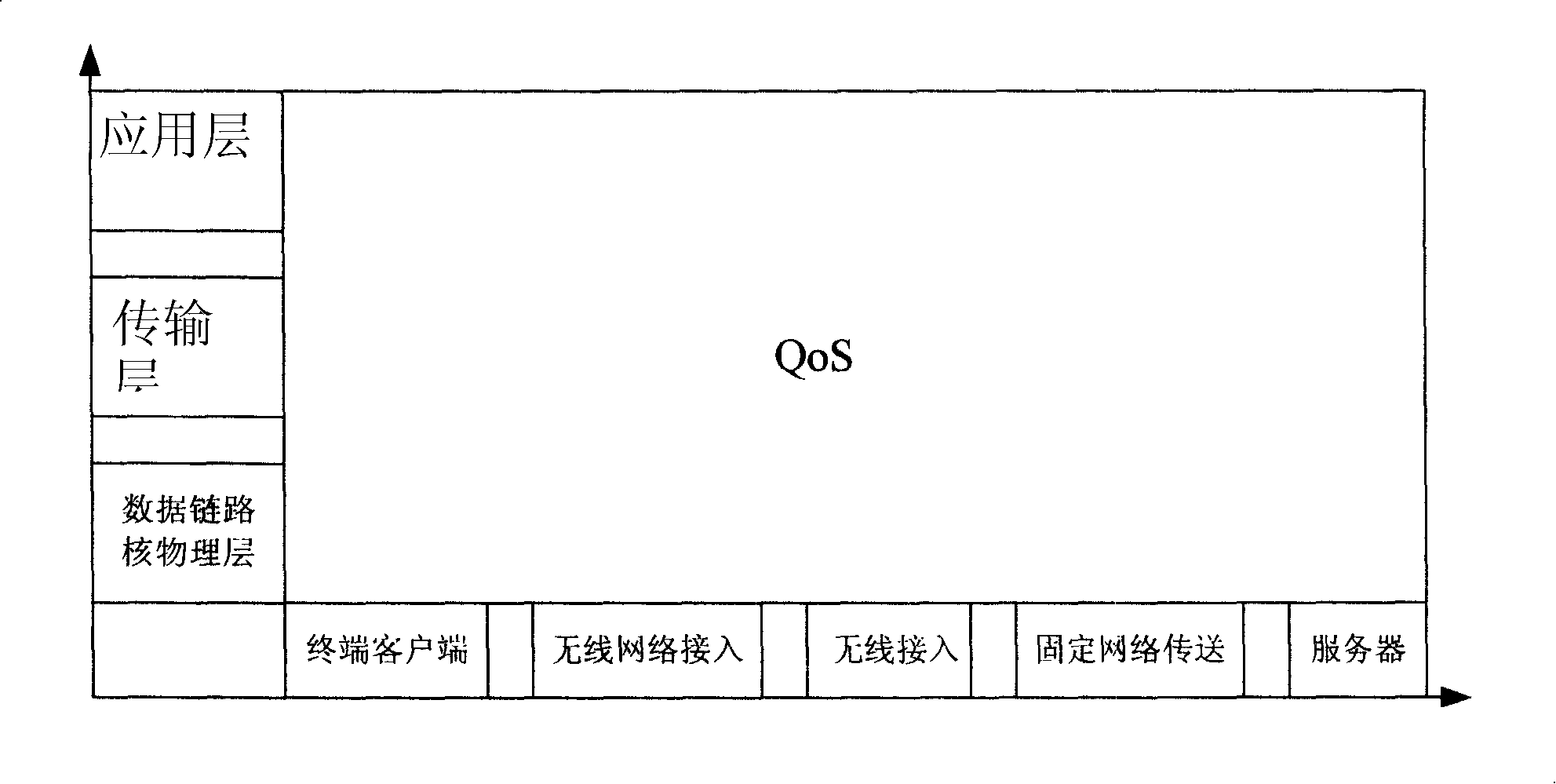
[0020] The present invention performs vertical and horizontal layering on QoS parameters according to the network level and different network elements, and maps the QoE parameters representing user experience with the layered QoS parameters in a certain rule, and establishes a mapping model. When developing a new service or optimizing an existing service, it is possible to perform optimal deployment of relevant network elements according to the actual capabilities of the network elements in the existing network from the perspective of user experience.

[0021] Such as figure 1 As shown, it is a schematic diagram of the inventive service quality layer model, and the network layer is vertically represented in the figure. The network layer here refers to the layer specified in the OSI network model, including the application layer, the transport layer, and the data link layer and physical layer. The network elements involved in the service are represented horizontally in the fig...


PUM


Abstract

The invention relates to a method used for automatic generation of net element allocation parameter, comprising the following steps: experience quality parameter selected according to predetermined service is input; according to a parameter mapping model of experience quality and service quality, the experience quality parameter is mapped to become the service quality parameter of each correlative net element inside a current service network; the service quality parameter of each correlative net element is compared with the acquired practical service quality level of the current service network, thereby obtaining a service quality parameter according with practical service quality level after adjustment. The method which establishes the mapping relations between different network hierarchies and different logic net elements forms a two-dimensional logical system; moreover, according to the two-dimensional logical system, the method establishes a mathematical model to analyze the quantification mapping relation between QoS parameter and QoE parameter; during selecting the QoE parameter, the selection is carried out through the testing and statistical analysis of a large sample according to the key factors of user survey and market research, thereby quantizing the relation between performance indexes.

Description

technical field [0001] The invention relates to a method for automatically generating network element deployment parameters in a mobile communication network, in particular to a method for automatically generating network element deployment parameters for end-to-end services in mobile communication. Background technique [0002] With the advancement of communication technology, end-to-end services are gradually developed. For all parties involved in mobile communications, such as operators, service providers, and equipment suppliers, the evaluation of end-to-end service performance is very important. For operators, end-to-end service performance evaluation is of great significance for further network deployment. At the present stage, there is still a lack of authoritative specifications input by standards organizations in this field. Although there are some related technical contents, they usually start from the perspective of engineering technology to conduct research and a...

Claims


Application Information

Patent Timeline
Patent Type & Authority Applications(China)
IPC IPC(8): H04Q7/38H04Q7/34H04L12/24H04L1/00H04L12/56
Inventor 张炎王敬宇王南掬杨若望
Owner CHINA MOBILE COMM GRP CO LTD
Learn More