
Device for transporting fuel

A technology for fuel and storage container, applied in the field of devices for conveying fuel, can solve the problem of high cost of wire hoops, and achieve the effects of easy installation and replacement, reduced manufacturing cost and installation cost, and reliable preloading

Active Publication Date: 2008-08-06
ROBERT BOSCH GMBH
View PDF0 Cites 2 Cited by
  • Summary
  • Abstract
  • Description
  • Claims
  • Application Information

AI Technical Summary

Problems solved by technology

Relatively high cost for wire hoops

Method used


Image

  • Device for transporting fuel
  • Device for transporting fuel
  • Device for transporting fuel

Examples


Embodiment Construction

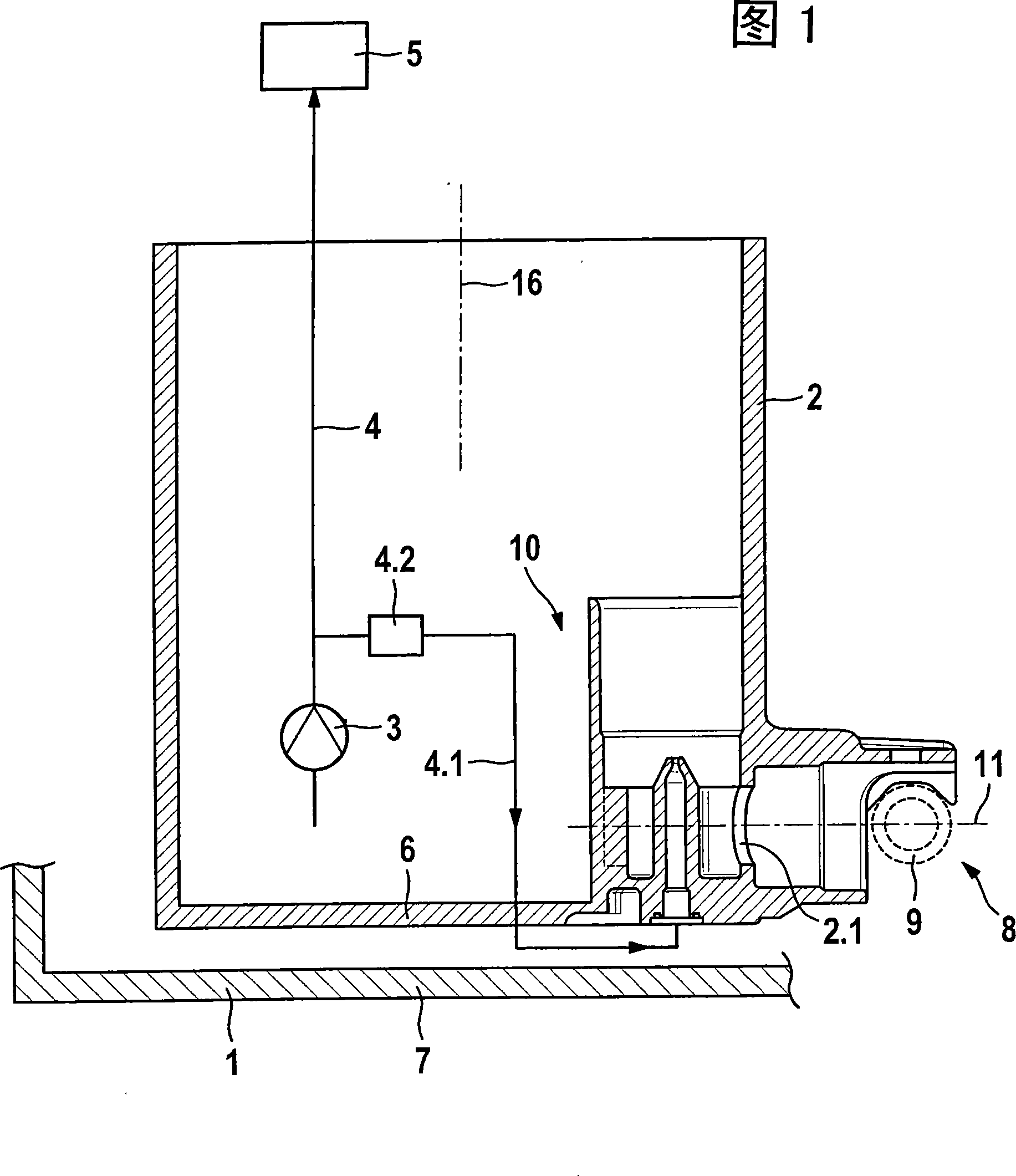
[0018] Figure 1 shows a simplified view in section of a device with a storage container according to the invention.

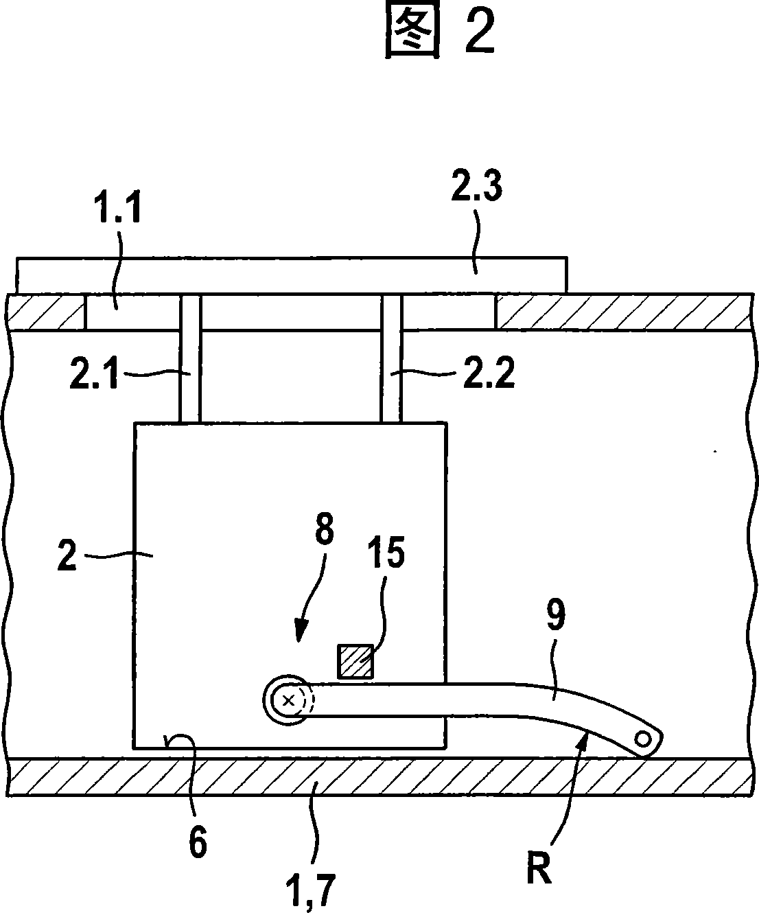
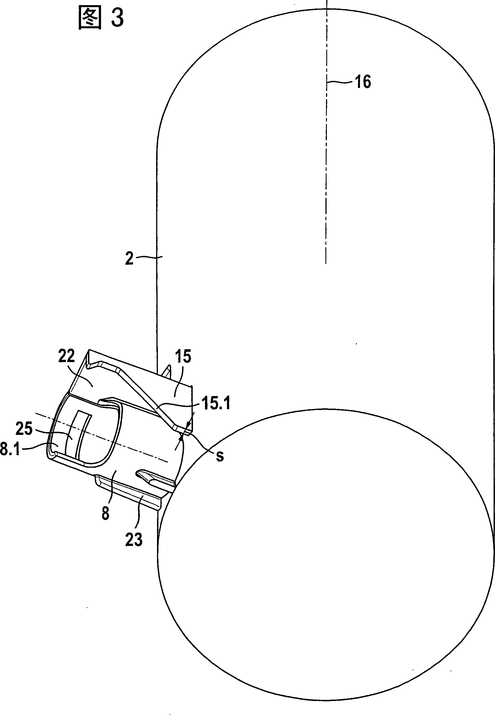
[0019] The device is housed in a fuel-filled storage tank 1 . It has a storage container 2 and a conveyor unit 3 , which is accommodated, for example, in the storage container 2 and draws fuel from the storage container. The feed unit 3 feeds the fuel under increased pressure via the pressure line 4 to the internal combustion engine 5 . Specifically, however, the conveyor assembly 3 can also be arranged outside the storage container 2 or storage container 1 . The storage container 2 is placed on the bottom 7 of the storage container 1 and serves to keep sufficient fuel around the conveyor assembly 3, so that even when the liquid level in the storage container 1 is low and when the vehicle accelerates, brakes, curves and And / or when driving on slopes, the conveyor unit can also suck fuel. The storage container 2 , which is, for example, pot-shaped, has a bott...


PUM


Abstract

The device has a delivering mechanism for sucking fuel from a storage container (2), and a suction line (9) supported at a connection of the storage container about a rotating axis in a rotatable manner, where the suction line has an impressed, curved, or bent shape. A dog for limiting rotatability of the suction line is provided in the storage container. The dog is arranged in such a manner thatthe suction line is prestressed against a base (7) at the storage container attached in the base, where the dog has a ridge shape, cylindrical shape, or cuboid shape.

Description

technical field [0001] The invention relates to a device for delivering fuel. Background technique [0002] Devices are known for feeding fuel from a fuel tank to an internal combustion engine, which have a storage container and an intake line mounted rotatably about an axis of rotation in a connection to the storage container. An injection pump sucks fuel from a region of the fuel tank remote from the storage container via the suction line. The end of the suction line facing away from the storage container must always be in contact with the bottom of the fuel tank, so that fuel can be sucked out even when the liquid level in the fuel tank is very low. The device therefore has a wire ferrule for depressing the suction catheter, which holds the suction catheter in a predetermined position. The wire hoop is fastened to the storage container and extends substantially parallel to the suction line. The suction catheter is designed to be elastically bendable and fastened to the...

Claims


Application Information

Patent Timeline
Patent Type & Authority Applications(China)
IPC IPC(8): F02M37/02
CPCB60K15/077B60K2015/03105B60K2015/03111B60K2015/03467
Inventor W·施奈德M·拜尔J·布赖德尔特T·威兰H-P·布劳恩W·W-D·金P·西格尔A·塞茨
Owner ROBERT BOSCH GMBH
Learn More