
Illuminating unit

A technology for lighting units and light guide sheets, which is applied in the direction of light guides, optical components, light guides, etc. of the lighting system to achieve the effect of improving brightness

Inactive Publication Date: 2008-07-30
ALPS ALPINE CO LTD
View PDF2 Cites 9 Cited by
  • Summary
  • Abstract
  • Description
  • Claims
  • Application Information

AI Technical Summary

Problems solved by technology

In this way, if the light guide sheet made of plastic material is used to guide the light of the light-emitting diode through the above-mentioned method, a specific component in the light will be absorbed, and there is a problem that it is difficult to make the entire surface emit light in a uniform color according to the position of the light source.

Method used


Image

  • Illuminating unit
  • Illuminating unit
  • Illuminating unit

Examples


Embodiment Construction

[0043] Hereinafter, embodiments of the present invention will be described in detail with reference to the drawings.

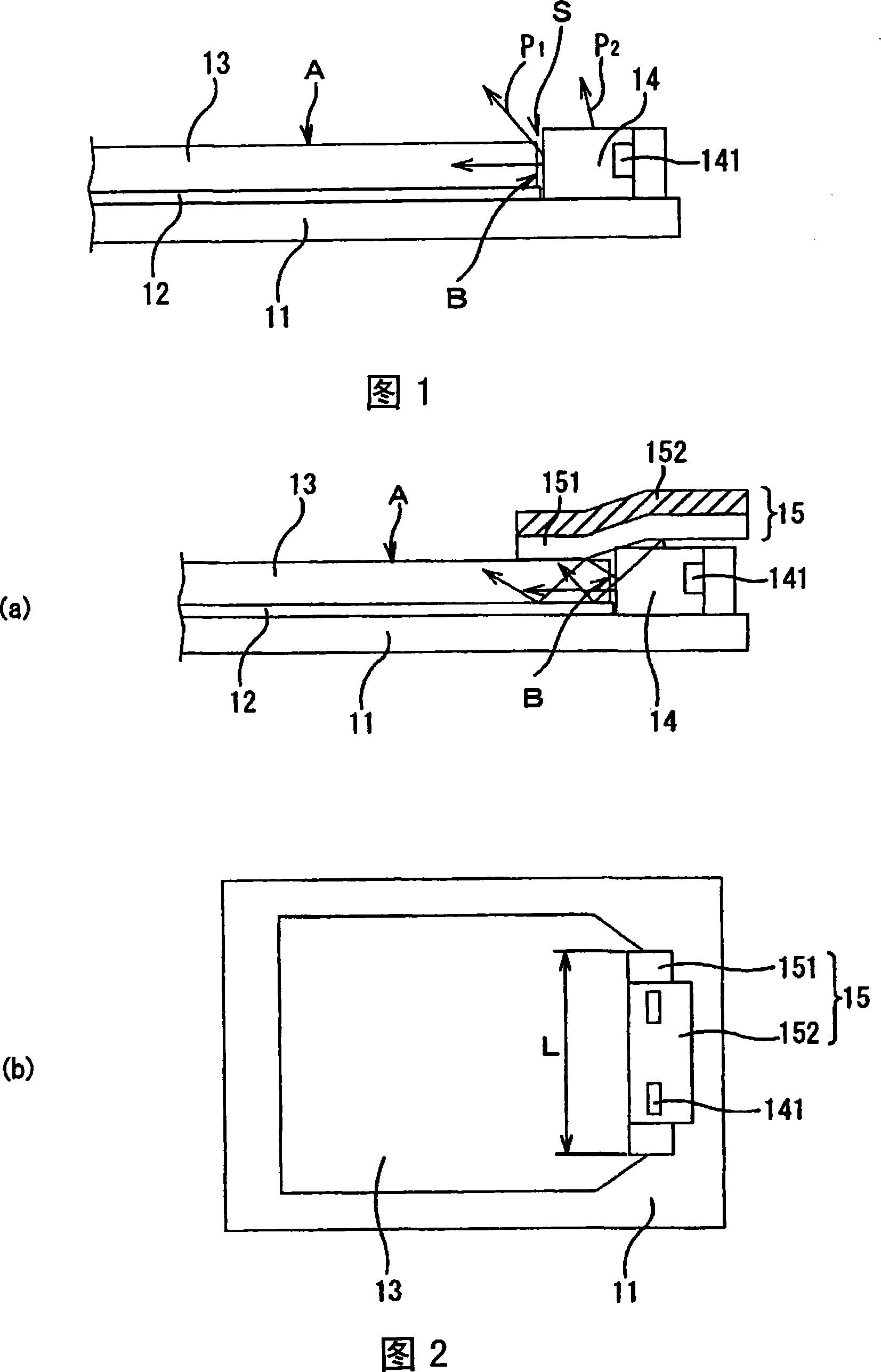
[0044] FIG. 1 is a diagram showing a lighting unit that does not have the structure according to the present invention. The lighting unit shown in FIG. 1 has a base body 11 with an operating area. There is no particular limitation on the configuration of the operation region of the base body 11 . Contact pads 12 are arranged on the base body 11 . The contact sheet 12 is made of a plastic material such as PET (polyethylene terephthalate) resin.

[0045] A light guide sheet 13 is arranged on the contact sheet 12 . In the vicinity of the end surface B of the light guide sheet 13, the light source unit 14 is arranged. A light emitting diode (LED) 141 as a light source is installed in the light source unit 14 . In order to reliably perform operations in the operation area (such as pressing of buttons), it is necessary to reduce the thickness of the light guide...


PUM


Abstract

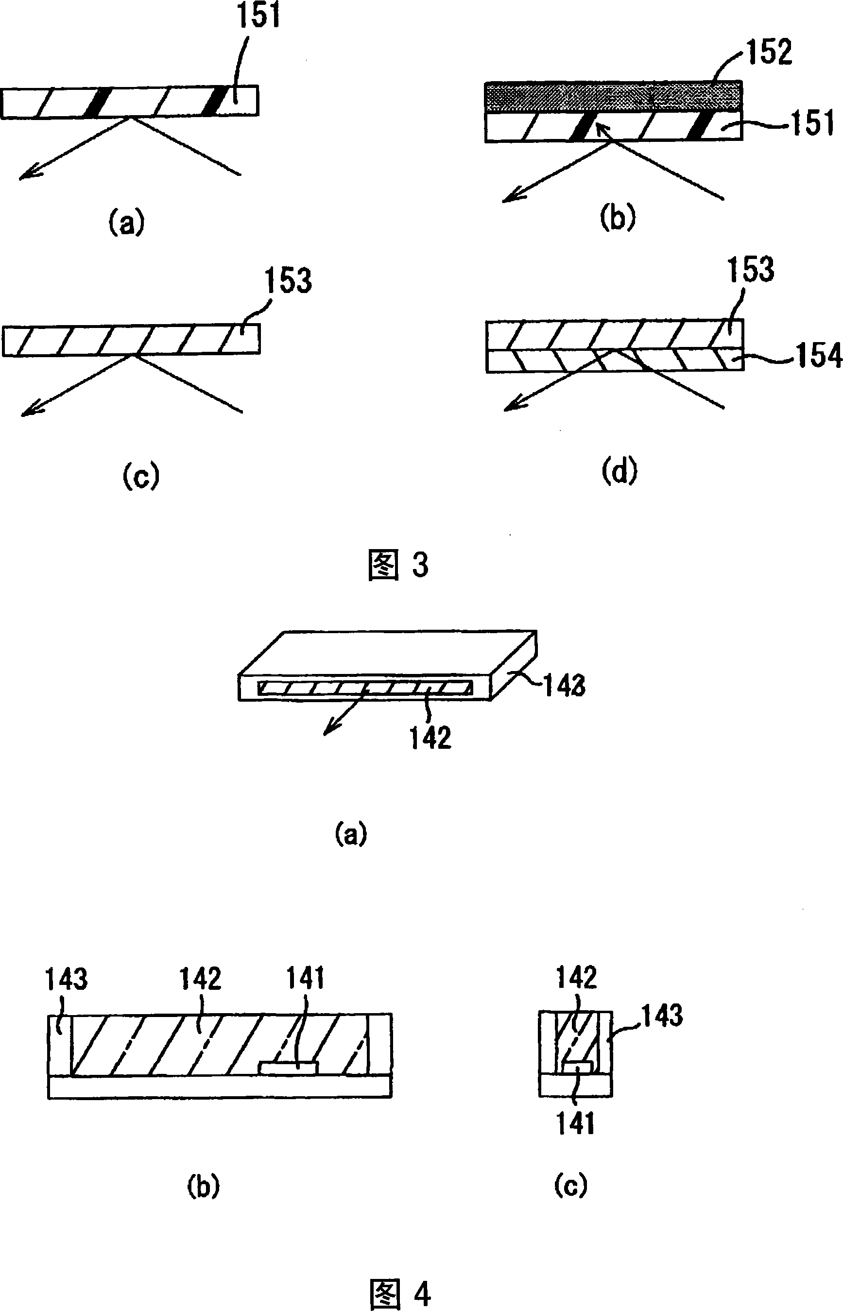
Disclosed is an illuminating unit capable of effectively introducing light emitted from a light source into a light guide sheet to improve the brightness of light and emitting uniform color light. Light emitted from a light emitting diode of a light source unit is incident on a side surface of a light guide sheet. A spacer aligns the emission center of the light emitting diode with the center of the light guide sheet in the thickness direction thereof. The incident light travels in the light guide sheet and is then diffused in light emitting regions provided on the main surface of the light guide sheet. Then, the diffused light is emitted to the outside. In addition, light components emitted from a gap between the light emitting diode and the side surface of the light guide sheet or light components emitted from the upper surface of the light source unit to the outside are reflected to the light guide sheet by a cover member.

Description

technical field [0001] The present invention relates to an illumination unit for illuminating an operation area of ​​a portable terminal device such as a mobile phone. Background technique [0002] Conventionally, as a display device, mainly an illumination mechanism of a liquid crystal display device, a planar light source that supplies light from the back side of a liquid crystal display panel toward the display surface side, such as a backlight device, is known. As such a backlight device, there is a device disclosed in Patent Document 1, for example. As disclosed in Patent Document 1, the thickness of light emitting diodes serving as light sources of the backlight device is approximately equal to or greater than the thickness of the wiring board. [0003] In addition, there is also a device disclosed in Patent Document 2, for example. The planar light source includes a light guide plate for guiding light from a light-emitting diode, and a transparent film having a fluo...

Claims


Application Information

Patent Timeline
IPC IPC(8): F21V8/00G02F1/13357G02F1/1335
Inventor 不藤平四郎黑木俊光杉浦琢郎日比野郁夫片山胜行吉田淳史渡边浩伸
Owner ALPS ALPINE CO LTD
Learn More