
Evacuation apparatus

A technology of evacuation device and vacuum pump, which is applied in the direction of space heating and ventilation, ventilation system, heating method, etc., to achieve the effect of improving the final pressure

Inactive Publication Date: 2008-07-30
ANEST IWATA CORP
View PDF1 Cites 9 Cited by
  • Summary
  • Abstract
  • Description
  • Claims
  • Application Information

AI Technical Summary

Problems solved by technology

Increasing the final pressure and securing the pumping speed are not mentioned in Patent Document 2

Method used


Image

  • Evacuation apparatus
  • Evacuation apparatus
  • Evacuation apparatus

Examples


Embodiment Construction

[0030] The invention will be described in more detail below with reference to the embodiments shown in the drawings. However, the dimensions, materials, shapes, relative positions, etc. of elements described in these embodiments are for illustration only, and should not be construed as limiting the scope of the present invention unless specifically stated.

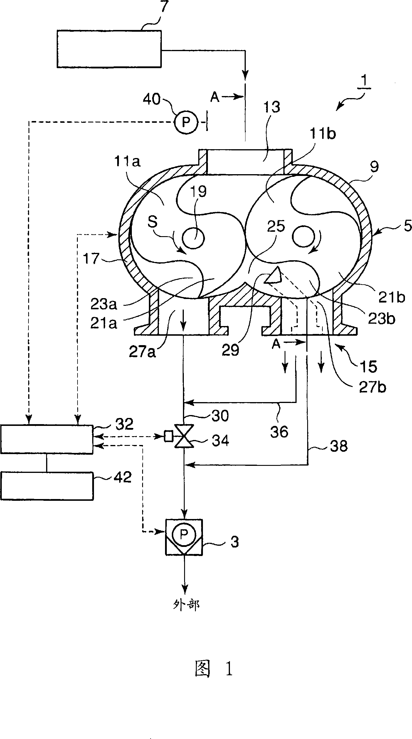
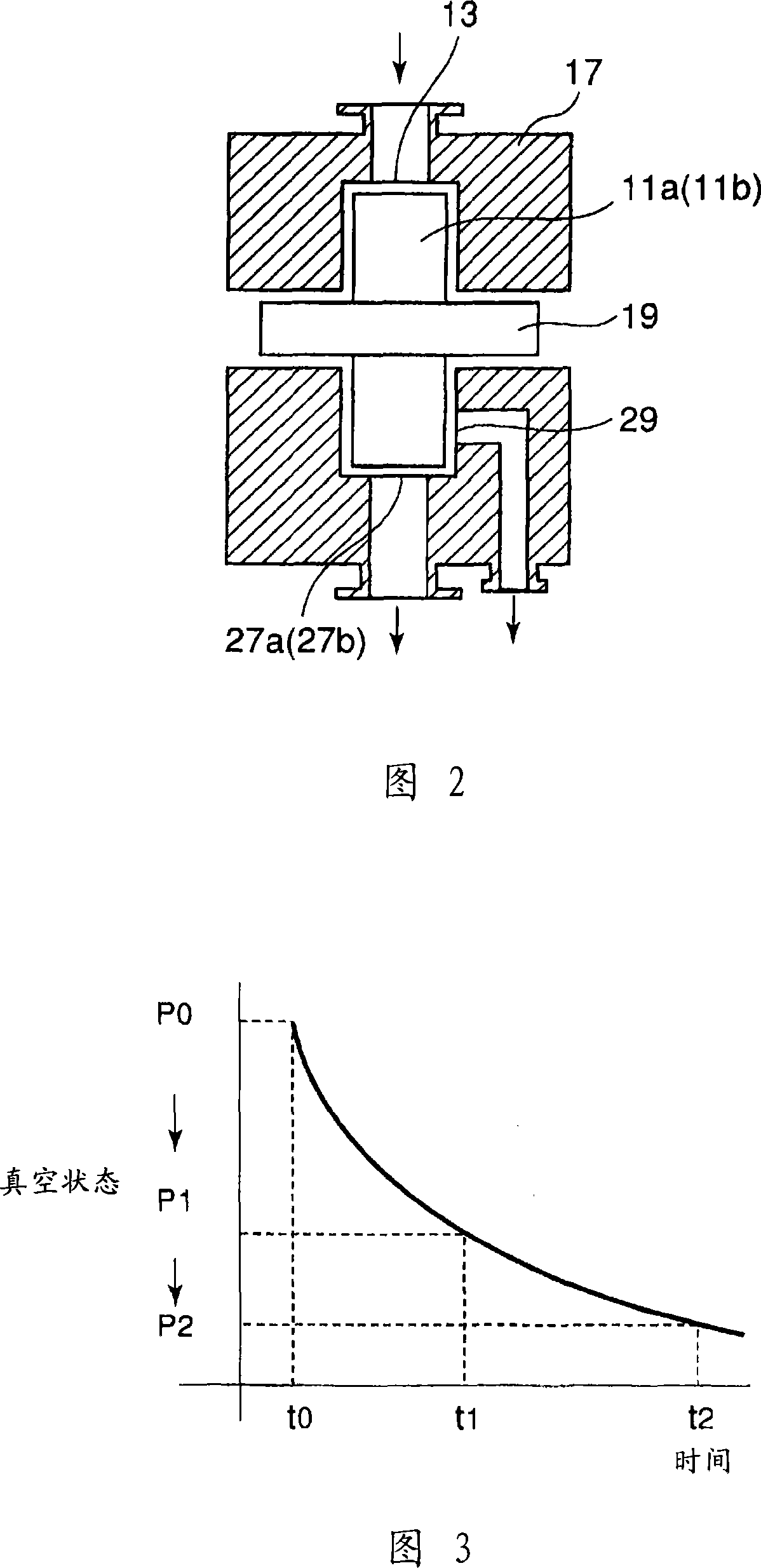
[0031] What Fig. 1 shows is the whole of the embodiment of the present invention, what Fig. 2 shows is the view of section A-A in Fig. 1.

[0032] As shown in FIG. 1 , the evacuation device 1 is equipped with an external vacuum pump (vacuum pump) 3 and a mechanical booster pump (mechanical booster pump for sucking vacuum) 5 provided on the upstream side of the vacuum pump 3 so that by operating the pump 3 and 5, obtain a vacuum in the vacuum box 7.

[0033] The mechanical booster pump 5 is a claw-type vacuum pump 9 including a pair of pump rotors 11 a and 11 b , a gas suction port 13 and a gas discharge port 15 . The mec...


PUM


Abstract

The invention discloses an evacuating device. It is used to evacuate tanks, cavities, etc., wherein a mechanical vacuum booster pump is provided on the upstream side of an external vacuum pump; wherein the mechanical booster pump has vent holes for discharging low-compressed gases and vent holes for discharging high-compressed gases Exhaust holes; wherein, when the external vacuum pump starts to discharge gas, the gas is sent to the external vacuum pump through all the vent holes for discharging low-compression gas and for discharging high-compression gas, when the pressure of the discharged gas is subsequently reached by the external vacuum pump At final pressure (medium vacuum), the gas is only delivered to the external vacuum pump through the vent hole for discharging highly compressed gas.

Description

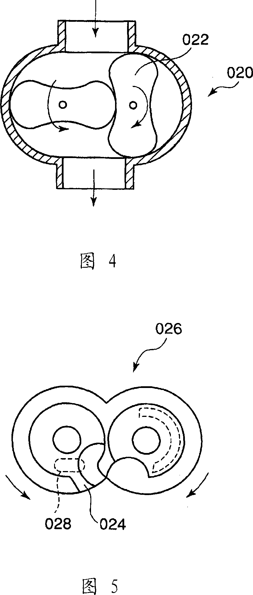
technical field [0001] The invention relates to an evacuation device for evacuating tanks, cavities, etc.; wherein a mechanical booster pump for evacuating vacuum is provided upstream of an external vacuum pump. Background technique [0002] In order to evacuate tanks, cavities, etc. at a high pumping speed, a mechanical booster pump for pumping vacuum is usually provided on the upstream side (vacuum side) of an external vacuum pump (booster pump) with a low pumping speed. For mechanical booster pumps, Roots vacuum pumps are usually used. Roots vacuum pumps perform compression / exhaust operations by rotating a pair of Roots-type vanes. [0003] If the Roots vacuum pump 020 shown in FIG. 4 is used, when the shafts of a pair of Roots rotors rotate in opposite directions to each other, suction and discharge of gas are performed by changing the volume of the closed space. However, due to the small compression ratio of the Roots rotor, the resulting pressure (reduced pressure) t...

Claims


Application Information

Patent Timeline
Patent Type & Authority Applications(China)
IPC IPC(8): F04C23/00F04C25/02F24F7/06
CPCF04C18/126F04C23/005F04C25/02F04C28/02F04C28/06F04C2220/12F04C2250/102
Inventor 谷川志郎中山贵光武藤龙介户田美奈子
Owner ANEST IWATA CORP
Learn More