


Quick Research
Generate reliable direction feasibility study reports for your R&D in just a few steps.

Technical Q&A
Discover and master advanced knowledge NOW. Basics, ideas, possibilities, all at once.

Find Solutions
As an expert in R&D theories, this can generate solutions to your technical problems instantly.

Evaluate Feasibility
Analyze your overall solution with one click, know your potential R&D risks in advance.

Monitor Landscape
Get weekly tech updates, stay abreast of the latest tech innovations and key insights.
Ventilation sole
A technology of natural ventilation and bottom surface, applied in the direction of soles, footwear, insoles, etc., can solve the problems of natural air circulation, easy inflow of external impurities, complicated structure, etc., to achieve the effect of impact degree protection, simple structure and low cost
- Summary
- Abstract
- Description
- Claims
- Application Information
AI Technical Summary
Problems solved by technology
Method used
Image

Examples
no. 1 example
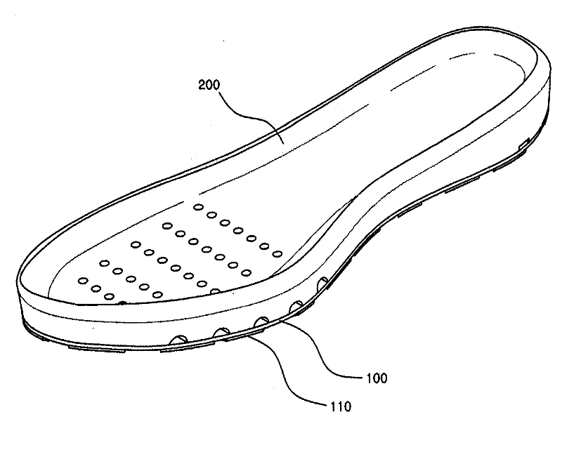
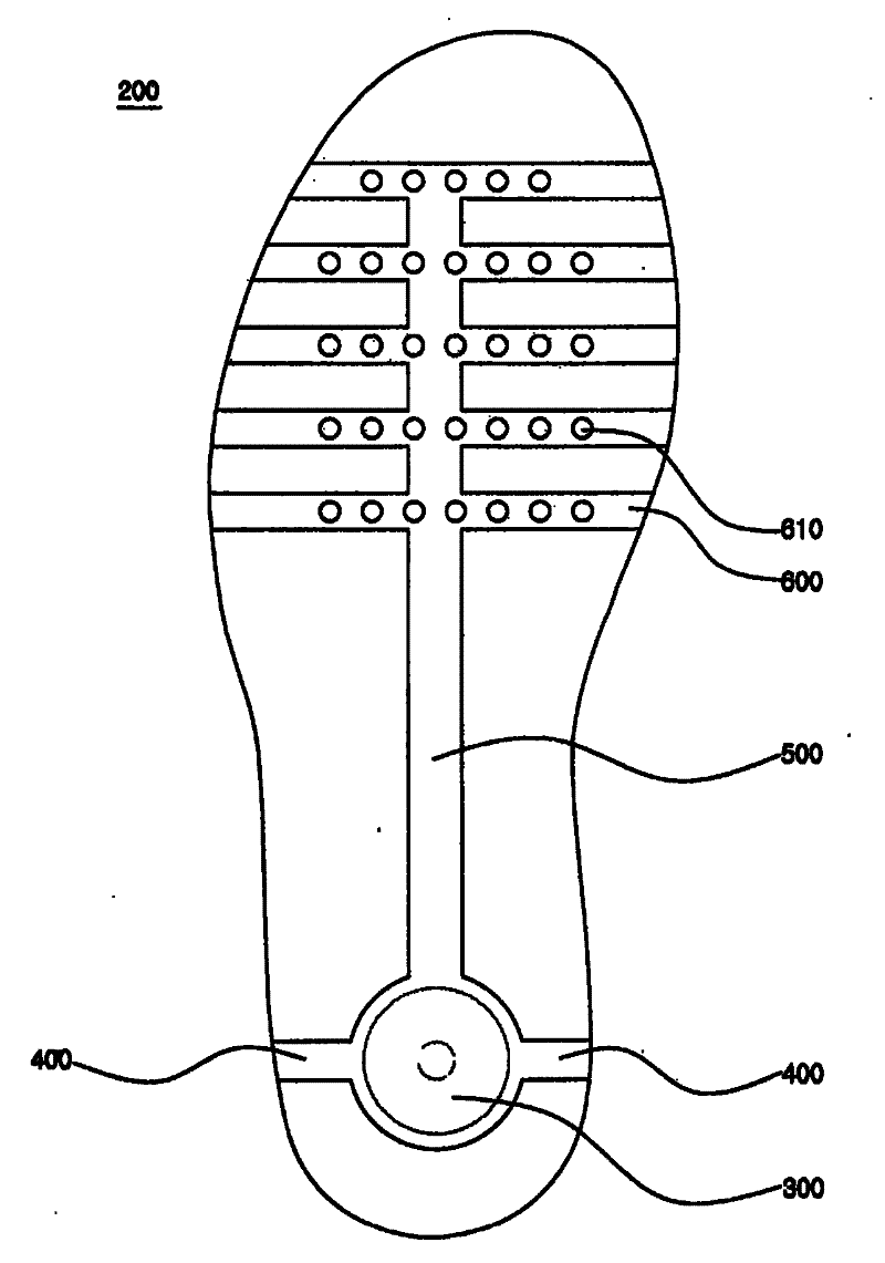
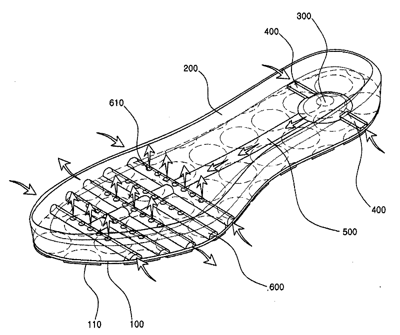
[0047] figure 1 is a perspective view of the ventilated sole of the first embodiment of the present invention; figure 2 It is a bottom view of the insole of the ventilated sole of the first embodiment of the present invention; figure 2 It is an example diagram of the action of the ventilated sole of the first embodiment of the present invention.
[0048] As shown in the figure, the ventilated sole of the first embodiment of the present invention includes: an outsole 100 , an insole 200 , a pump unit 300 , an air inflow portion 400 , an air moving path 500 and an air outflow portion 600 . That is to say, the ventilated shoe sole of the present invention is composed of the outsole 100 and the insole 200 combined with the outsole 100, and the pump unit 300, the air inflow part 400, the air moving path 500 and the air outflow part 600 formed by the above combination. consist of.
[0049] Firstly, the above-mentioned outsole 100 is generally made of rubber, and the bottom surf...
no. 2 example
[0063] Figure 4 It is a perspective view of the ventilated sole of the second embodiment of the present invention; Figure 5 It is a bottom perspective view of the inner bottom of the ventilated sole according to the second embodiment of the present invention; Image 6 It is a top perspective view of the inner bottom of the ventilated sole according to the second embodiment of the present invention; Figure 7 It is a top perspective view of the outsole of the ventilated sole according to the second embodiment of the present invention; Figure 8 It is an example diagram of the action of the ventilated sole of the second embodiment of the present invention.
[0064] As shown in the figure, the ventilated sole of the second embodiment of the present invention includes an outsole 100 , an insole 200 , a pump unit 300 , an air inflow part 400 , an air moving path 500 and an air outflow part 600 . That is to say, the ventilated shoe sole of the present invention is composed of t...
PUM
 Abstract
Description
Claims
Application Information
 - R&D Engineer
- R&D Manager
- IP Professional
- Industry Leading Data Capabilities
- Powerful AI technology
- Patent DNA Extraction
Browse by: Latest US Patents, China's latest patents, Technical Efficacy Thesaurus, Application Domain, Technology Topic, Popular Technical Reports.
© 2024 PatSnap. All rights reserved.Legal|Privacy policy|Modern Slavery Act Transparency Statement|Sitemap|About US| Contact US: help@patsnap.com