
Reflection type polarization irrespective miniaturization photo-electricity mutual-inductor

A photoelectric transformer, magneto-optical technology, applied in the direction of the magnitude/direction of the magnetic field, instruments, optics, etc., can solve the problems of polarization state disturbance cannot be eliminated, poor beam quality, coupling difficulties, etc., to achieve polarization-independent, convenient and low-cost Ease of cost reduction and miniaturization

Inactive Publication Date: 2008-07-23
WUHAN CHENGSI HIGH TECH
View PDF10 Cites 23 Cited by
  • Summary
  • Abstract
  • Description
  • Claims
  • Application Information

AI Technical Summary

Problems solved by technology

(3) The linear birefringence distribution introduced by the stress that changes with the change of temperature will cause the measurement sensitivity of the sensor to drift with the change of temperature, and the distribution of sensitivity in the sensor head is non-uniform, so that the signal output will not only be affected by the The modulation of the position of the measured conductor, and it will also be disturbed by the external large magnetic field
[0006] An improved all-fiber sensing head is disclosed in U.S. Patent No. 5,463,312 by minimizing the birefringence of the sensing fiber during fabrication (e.g. by spinning the fiber) followed by annealing the coil form to minimize the temperature dependence To improve the sensitivity of the all-fiber current transformer, but it cannot completely eliminate the influence of various types of fiber birefringence or polarization disturbance caused by the birefringence effect
The international patent WO1997 / 019367 uses polarization-maintaining optical fiber to connect multiple straight optical fiber sensing heads to eliminate the change of polarization state caused by temperature-related birefringence and improve the responsivity of the sensing head. The influence of its own birefringence and the position of the incident polarization plane, and the design of the sensor head is complicated
In the international patent WO2002 / 004963 and the Chinese patent "All Optical Fiber Current Test Method" (publication number CN1488946A, published on April 14, 2004), the method of interference is used to fundamentally solve the problem of polarization disturbance based on the Faraday effect, but This technology makes the sensor complex and the cost rises sharply. Moreover, it must ensure that the optical paths of the two coherent beams are the same, so it is impossible to avoid the influence of optical path changes caused by birefringence such as temperature and stress.
[0007] Chinese patent "An Optical Current Sensor" (publication number CN2403033Y, published on October 25, 2000), Chinese patent "Double Incident Optical Path Reverse Optical Current Sensor" (publication number CN2319815Y, published on May 19, 1999) ), the Chinese patent "Double Optical Path Optical Current Sensor Head" (publication number CN2762147Y, date of publication on March 1, 2006), etc. have all disclosed a sensor head based on bulk optical glass, although this type of technology does not exist The birefringence introduced by the bending of the optical fiber sensing head, but the stress birefringence in the conducting fiber will cause the polarization state of the transmitted light to change with vibration, temperature and other factors, which is manifested as a change in intensity in the optical sensing head and photodetector , thereby introducing noise; at the same time, the linear birefringence formed by the residual stress of the optical glass material itself changes with temperature, and in practice, the birefringence caused by the additional stress introduced when installing and assembling optical path devices (such as lenses, polarizers, etc.) is at 60 The output drift caused by the temperature range of ℃ cannot be ignored; in addition, the sensor head made of magneto-optical glass is more complicated to process, and because of the long optical path, the beam quality is poor, the coupling is difficult, and the coupling efficiency is low (generally 1% to 2%)
[0008] In the sensor head of the magnetic field sensor type, the Chinese patent "A Photoelectric DC Current Sensor" (publication number CN1580789A, published on February 6, 2005) discloses a photoelectric DC current transformer, which adopts a dual light source symmetrical optical path structure to eliminate the light intensity drift of the light source, but this patent cannot eliminate the influence of polarization state disturbance on sensitivity
The Chinese patent "A Photoelectric Current Transformer" (publication number CN1271413C, published on August 23, 2006) introduces the method of adding a standard magnetic field to two sensor heads to eliminate the influence of temperature, but it does not affect the polarization state disturbance. It cannot be eliminated. This technology not only makes the sensor head complex and expensive, but also the standard magnetic field introduced is in other magnetic field environments for a long time, and the stability cannot be guaranteed.
In the Chinese patent "Comprehensive Compensation Fiber Optic Current Sensor" (publication number CN1093640C, published on October 30, 2002), a polarizing beam splitter is introduced to reduce the polarization correlation problem of the sensing head itself, but because of its input The output optical path is not the same, so the radial effect of the entire optical path cannot be compensated. The sensitivity of the sensor head will be disturbed by the external environment (such as temperature, stress, etc.) on the input and output optical fibers. The signal light is deflected by the magnetic field of the Faraday element and is lost by the temperature-sensitive element, which will cause the extinction ratio to be too large and cause the photodetector to fail

Method used


Image

  • Reflection type polarization irrespective miniaturization photo-electricity mutual-inductor
  • Reflection type polarization irrespective miniaturization photo-electricity mutual-inductor

Examples


Embodiment Construction

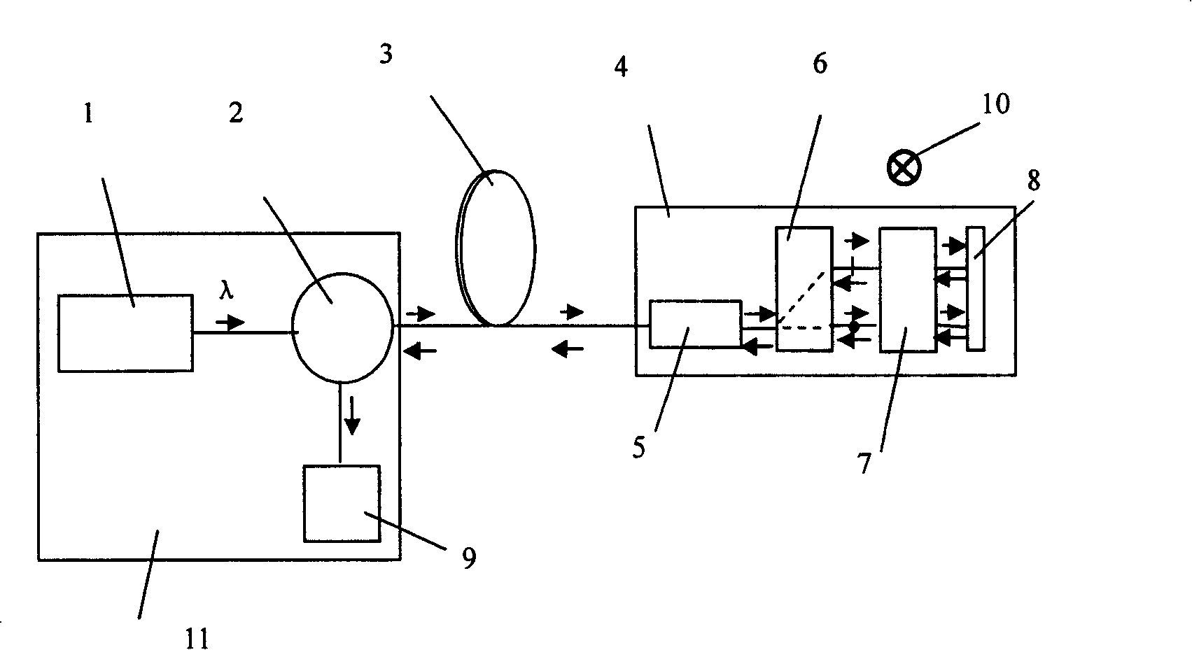
[0016] Below, the present invention will be further described in conjunction with the accompanying drawings.

[0017] exist figure 1 Among them, the light source 1, the light directional transmission device 2 and the photodetector 9 form a photoelectric processing unit 11, and the photoelectric processing unit 11 is connected with the sensor head 4 through the transmission fiber 3, and the sensor head 4 is composed of a collimator 5, a polarizing beam splitter The device 6, the magneto-optical Faraday element 7 and the reflector 8 are connected in sequence. And it is placed perpendicular to the wire 10 to be tested. At this time, the direction of the magnetic field generated by the current of the wire 10 to be tested is parallel to the direction of the optical path in the sensor head 4 .

[0018] The function of the collimator 5 is to collimate the signal light passing through the transmission fiber 3 so that it is vertically incident on the polarizing beam splitter 6 . The ...


PUM


Abstract

The invention relates to an optical fiber current mutual inductor, which comprises a photoelectric processor, a transmission optical fiber and a sensor head. The invention can utilize general transmission optical fiber, insulate the sensor head from the polarization disturbance caused by the double refraction of the transmission optical fiber via the polarization self-compensation structure of the sensor head, and make the input and output optical fibers same via adding one light directed transmitter in the photoelectric processor and arranging a reflector in the sensor head to effectively counteract the radial effect of optical path. The reflective structure can pass linearly-polarized light through magnetooptical Faraday component of two times to improve one power of current detection sensitivity and reduce the volume of the sensor head. The invention is suitable for measuring high-voltage large current of electric power system and is suitable for batch production of miniaturized photoelectric mutual inductor with low cost.

Description

technical field [0001] The invention relates to an optical fiber current transformer, more specifically, a polarization-independent miniaturized optical fiber current transformer. Background technique [0002] The optical current transformer (OCT for short) is based on the Faraday magneto-optic effect. It determines the current by measuring the angle at which the polarization plane of the light wave passes through the magneto-optic material due to the magnetic field generated by the current. size. Compared with the traditional current transformer (CT for short), OCT has many advantages: (1) It does not contain oil, and there is no risk of explosion; (2) It does not contain AC coils, and there is no risk of open circuit of the output coil, and it can be used to measure DC; (3) No iron core, no ferromagnetic resonance and hysteresis effect; (4) Anti-electromagnetic interference; (5) Small size, light weight, easy to install; (6) Completely isolated from high-voltage lines, sa...

Claims


Application Information

Patent Timeline
IPC IPC(8): G01R15/24G01R33/032G01R19/00G02F1/09G02F1/095
Inventor 肖礼蒋俏峰宋琼霞何学海
Owner WUHAN CHENGSI HIGH TECH
Learn More