


Quick Research
Generate reliable direction feasibility study reports for your R&D in just a few steps.

Technical Q&A
Discover and master advanced knowledge NOW. Basics, ideas, possibilities, all at once.

Find Solutions
As an expert in R&D theories, this can generate solutions to your technical problems instantly.

Evaluate Feasibility
Analyze your overall solution with one click, know your potential R&D risks in advance.

Monitor Landscape
Get weekly tech updates, stay abreast of the latest tech innovations and key insights.
Biomass chain combusting boiler backfire-proof material feeding device
A chain boiler and feeding device technology, applied in the direction of combustion method, combustion equipment, fuel supply, etc., can solve the problems of easy backfire and fast biomass burning speed, and achieve the effect of avoiding fast burning speed and guaranteeing safe operation
- Summary
- Abstract
- Description
- Claims
- Application Information
AI Technical Summary
Problems solved by technology
Method used
Image

Examples
specific Embodiment approach 1
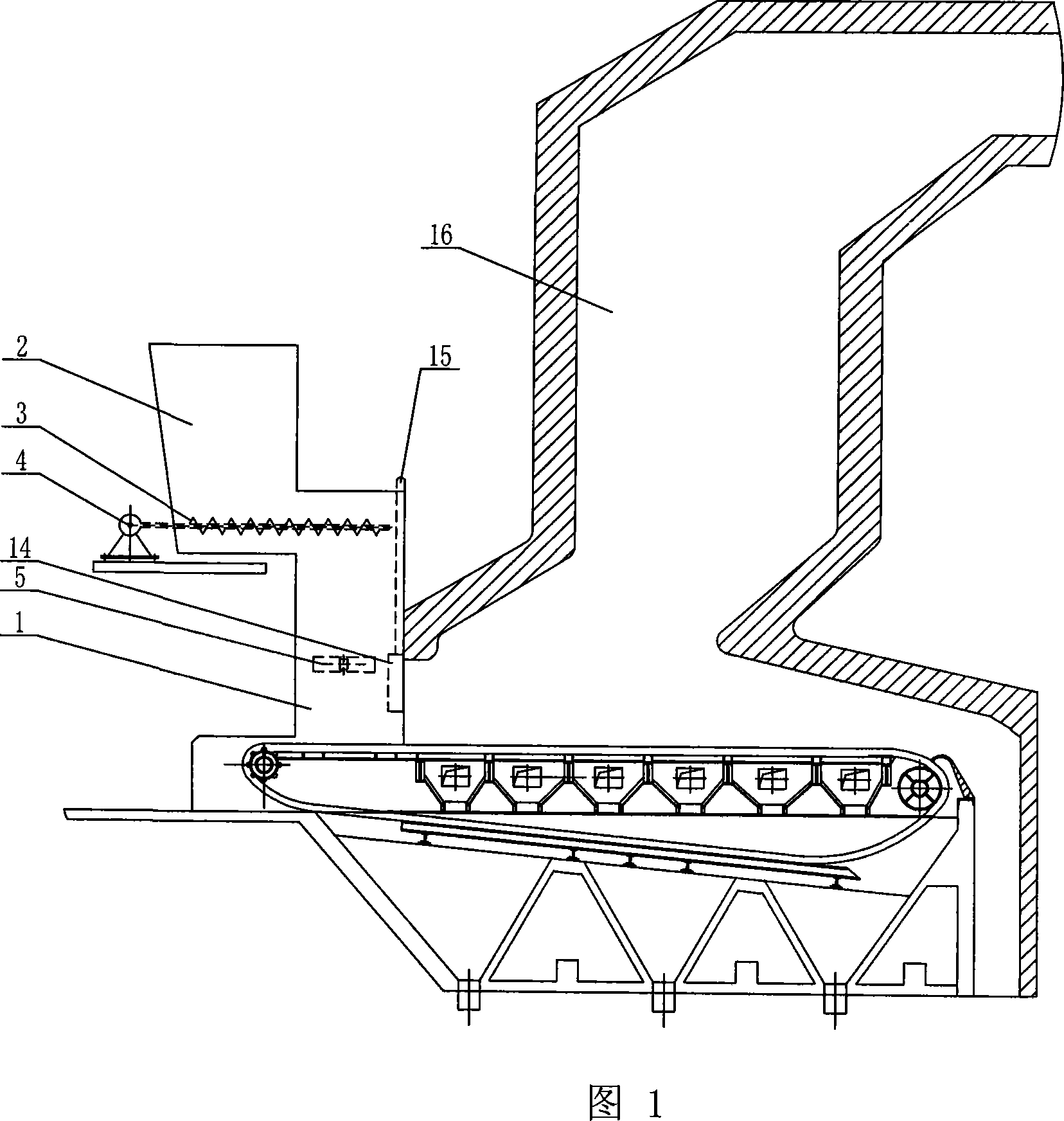
[0007] Specific embodiment 1: This embodiment is described in conjunction with FIG. 1. This embodiment is composed of a biomass lower hopper 1, a biomass upper hopper 2, an auger 3, a motor 4, and a boiler 16. The biomass upper hopper 2 is set on the biomass The left end surface of the upper end of the material lower hopper 1, and the biomass lower hopper 1 communicates with the biomass upper hopper 2, and the auger 3 extends into the biomass lower hopper 1 from the left end surface of the lower end of the biomass upper hopper 2 In the biomass upper hopper 2 , the left end of the auger 3 is connected to the motor 4 , and the biomass lower hopper 1 is arranged on the left end surface of the boiler 16 .
specific Embodiment approach 2
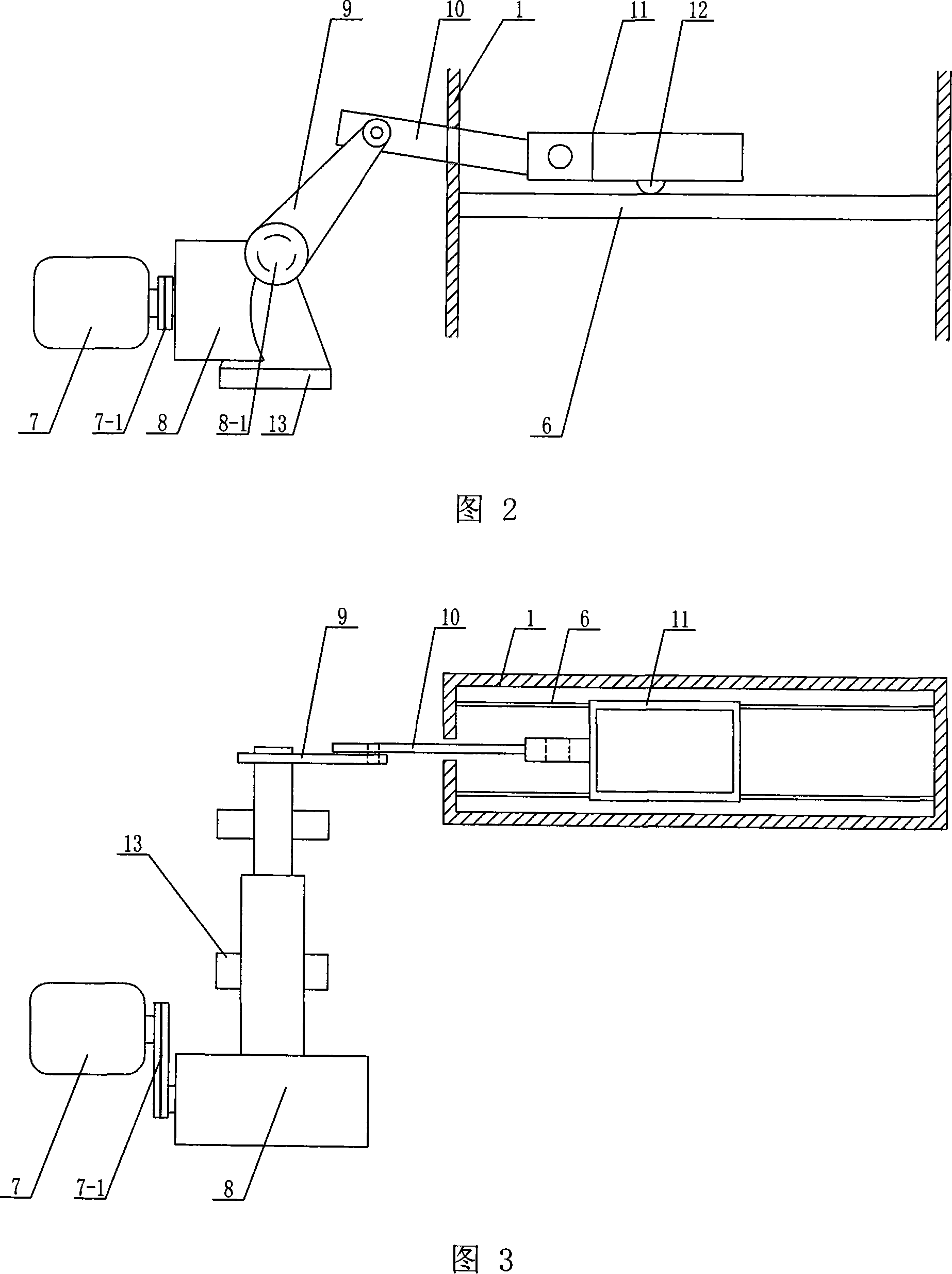
[0008] Specific embodiment 2: This embodiment is described in conjunction with Fig. 1 to Fig. 3. The difference between this embodiment and specific embodiment 1 is that the present invention also adds a pusher 5 and a guide rail 6, and the pusher 5 is driven by a motor 7. Reducer 8, crank 9, connecting rod 10, rake 11, roller 12 and support 13, the pulley 7-1 of the motor 7 is connected to the reducer 8, the output shaft 8-1 of the reducer 8 1 is hinged with the lower end of the crank 9, the upper end of the crank 9 is hinged with the connecting rod 10, the right end of the connecting rod 10 passes through the side wall of the biomass lower hopper 1 and is hinged with the target car 11, and the roller 12 is installed under the target car 11 end surface, and slide on the guide rail 6, the two ends of the guide rail 6 are respectively fixed on the front end surface and the rear end surface of the biomass lower hopper 1, and the lower part of the reducer 8 is provided with a supp...
specific Embodiment approach 3
[0009] Specific embodiment 3: This embodiment is described in conjunction with Fig. 1. The difference between this embodiment and specific embodiment 1 is that the present invention also adds a biomass baffle 14, and the biomass baffle 14 is arranged in a biomass lower hopper 1 on the right inner wall. With such arrangement, the thickness of the biomass fuel can be adjusted. Other compositions and connections are the same as in the first embodiment.
PUM
 Abstract
Description
Claims
Application Information
 - R&D Engineer
- R&D Manager
- IP Professional
- Industry Leading Data Capabilities
- Powerful AI technology
- Patent DNA Extraction
Browse by: Latest US Patents, China's latest patents, Technical Efficacy Thesaurus, Application Domain, Technology Topic, Popular Technical Reports.
© 2024 PatSnap. All rights reserved.Legal|Privacy policy|Modern Slavery Act Transparency Statement|Sitemap|About US| Contact US: help@patsnap.com