Detachable pipe joint

A technology for connectors and pipes, applied in the direction of pipes/pipe joints/fittings, flange connections, sleeve/socket connections, etc., can solve problems such as reduced production efficiency, difficult operation, and reduced work efficiency, so as to save production costs, Improved durability and high work efficiency

Inactive Publication Date: 2008-07-09
禹扬浩
View PDF0 Cites 8 Cited by
  • Summary
  • Abstract
  • Description
  • Claims
  • Application Information

AI Technical Summary

Problems solved by technology

In the above flange connection method, a flange with a certain width is provided in the circumferential direction of the pipe end, and gaskets are inserted into the pipe connection, and then fixed with multiple bolts, which requires increasing the width of the flange to be able to fit on the pipe end. The width of the bolts is not used at all, so that the material weight increases accordingly, and many bolt holes need to be machined, so the production efficiency is reduced and the production unit price is increased. When performing connection work, it is necessary to tighten multiple bolts, and at the same time, it is required to tighten the bolts evenly , thus significantly reducing work efficiency
In addition, when disassembling and assembling the connection parts, the bolts are often worn or damaged, which makes the operation difficult.
[0004] In order to improve these problems, there have been connecting pipes that can realize flange sealing and connection without using bolts. One fixing part of the O-ring is inserted so that the above-mentioned insertion part is inserted into one side part, and the fixing part provided on one side and the flange provided on the other side part are butted and fixed by a jig , when subjected to high water pressure, the insertion part becomes loose to cause water leakage or rupture; and there have also been cases where the flange provided at the front end of the connecting pipe can be inserted into the groove part at the same time, and at both ends of the connecting plate Set the hook part and the hook receiving part so that the hook part is hooked on the hook receiving part, which can withstand low water pressure but cannot withstand high water pressure, which is prone to water leakage or damage

Method used


Image

  • Detachable pipe joint
  • Detachable pipe joint
  • Detachable pipe joint

Examples


Embodiment Construction

[0015] Hereinafter, the present invention will be described in detail with reference to the accompanying drawings.

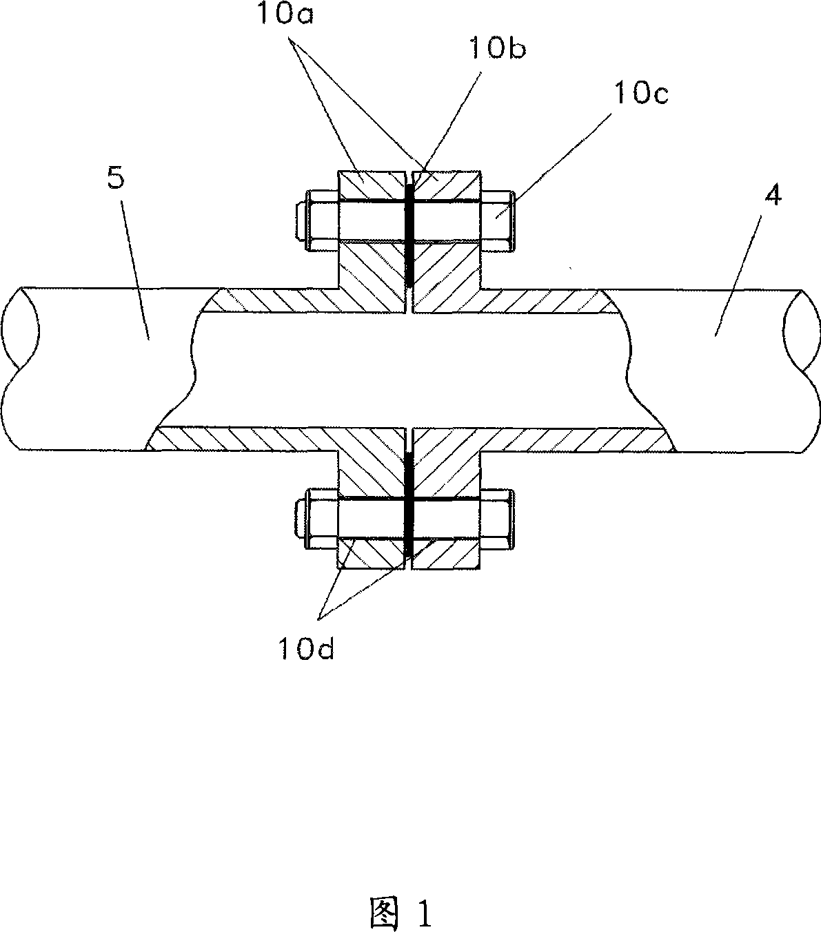
[0016] Figure 1 illustrates the existing flange connection method. For the connection of medium and large connecting pipes 4 and 5, it is difficult to use tapered bolts for processing. flanges 10a, and machine a plurality of bolt holes 10b on the flanges, and insert gaskets 10b between the flanges 10a for the sealing connection, and then use a plurality of bolts 10c to bond and fix.

[0017] The above-mentioned connection method needs to tighten a plurality of bolts 10c, thus requiring a long working time, and the bolts 10c are likely to be worn or broken during the process. And a wider flange 10a is required to use the bolt 10c, which increases the material weight, and also requires machining a plurality of bolt holes, thereby increasing the production unit price.

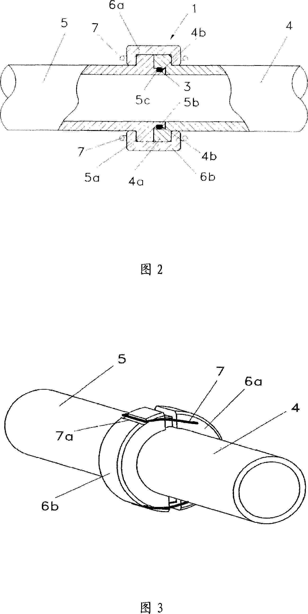
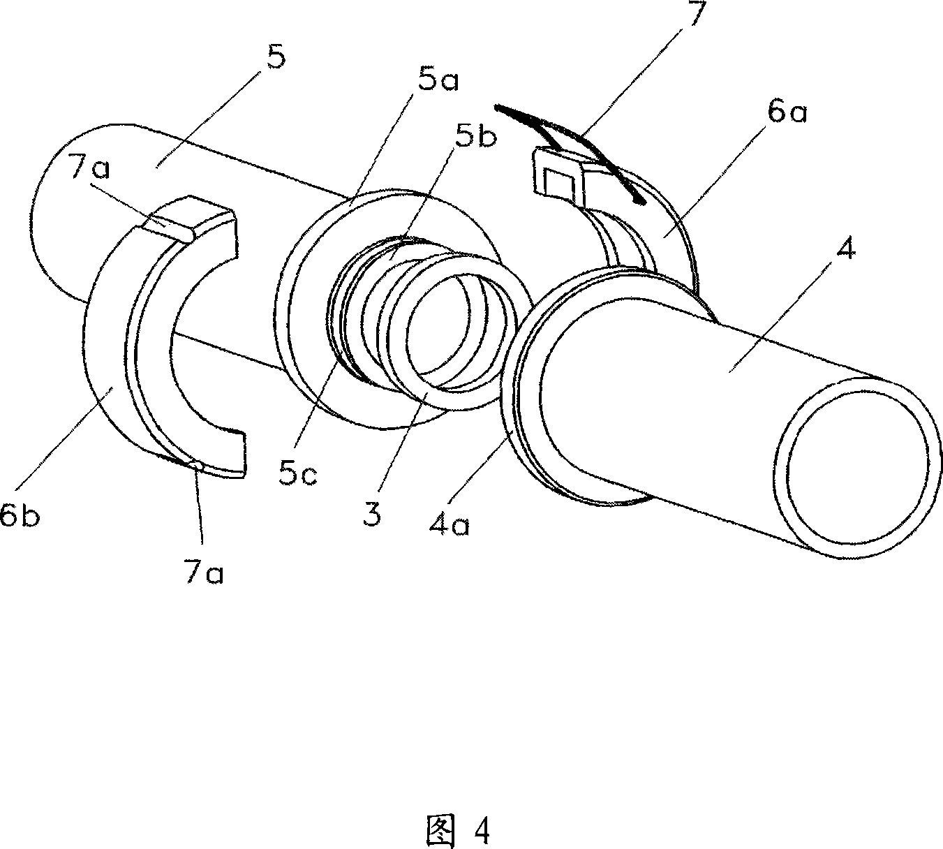
[0018] The connection method of the present invention does not need to tighten the bolt 10c. As...


PUM


Abstract

The invention provides a pipe connector that is easy to assemble and disassemble, and relates to the connector. The pipe connector can be assembled and disassembled relatively easily, and can significantly save production costs. The same protruding ring with a certain width is provided in the circumferential direction of both ends of the connecting pipe that constitutes the connecting piece body of the pipeline. Ordinary fixing devices are arranged in the opposite direction, and grooves for hooking the above-mentioned fixing devices are arranged on both ends of the connecting piece on the other side, and protrusions and O-ring grooves are arranged on the ends of the connecting pipes on the above-mentioned side , and the end of the connecting pipe on the other side is provided with a recessed portion adjacent to the above protruding portion, so that the other side of the O-ring inserted into the O-ring groove abuts against the inner peripheral surface of the recessed portion of the connecting pipe on to achieve a seal. The invention is not only easy to assemble and disassemble, but also has high working efficiency, improves durability, and can significantly save the production cost of the connecting piece.

Description

technical field [0001] The invention relates to a connecting piece, in particular to a pipe joint which is easy to assemble and disassemble. Background technique [0002] Existing pipeline connection methods include methods such as bolt connections and flange connections that can be disassembled at will, and methods such as welding connections that cannot be disassembled at will. [0003] In the above method, various equipment such as valves, pumps, filters, and heat exchangers are installed in the middle of the pipeline, and such equipment needs to be replaced. Therefore, bolt connections and flange connections that can be disassembled at will are usually used. Medium and large pipes are difficult to connect with bolts, so flange connections are used. In the above flange connection method, a flange with a certain width is provided in the circumferential direction of the pipe end, and gaskets are inserted into the pipe connection, and then fixed with multiple bolts, which r...

Claims


Application Information

Patent Timeline
Patent Type & Authority Applications(China)
IPC IPC(8): F16L23/032F16L23/036F16L23/18
CPCF16L23/04F16L21/00F16L21/06
Inventor 禹扬浩
Owner 禹扬浩
Why Eureka
Try Eureka