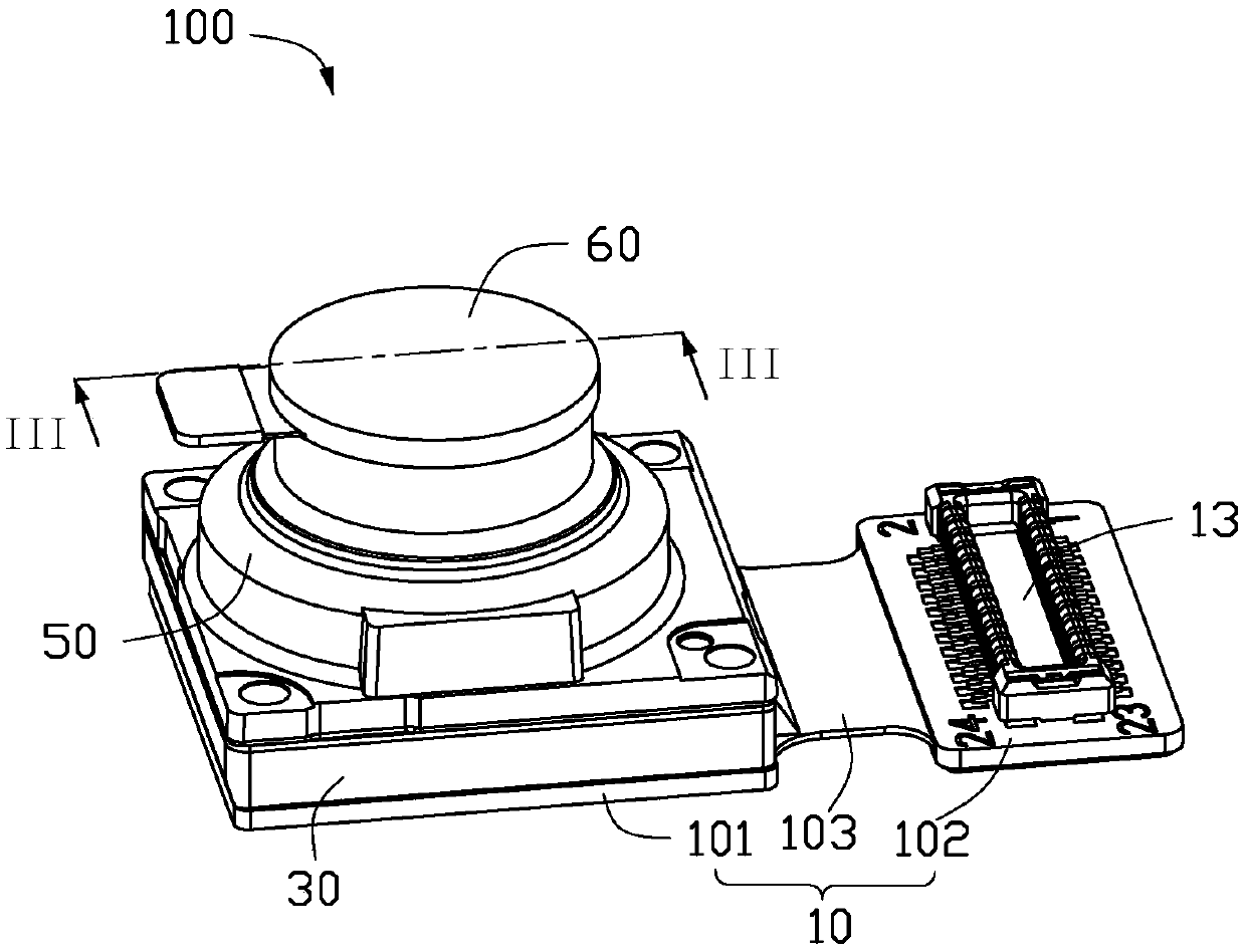
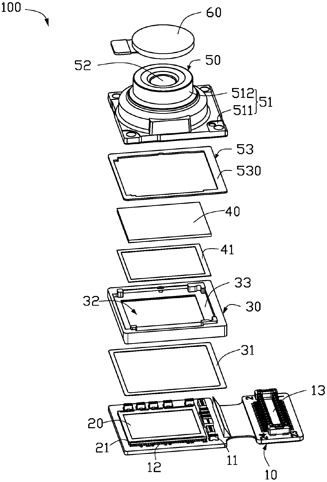
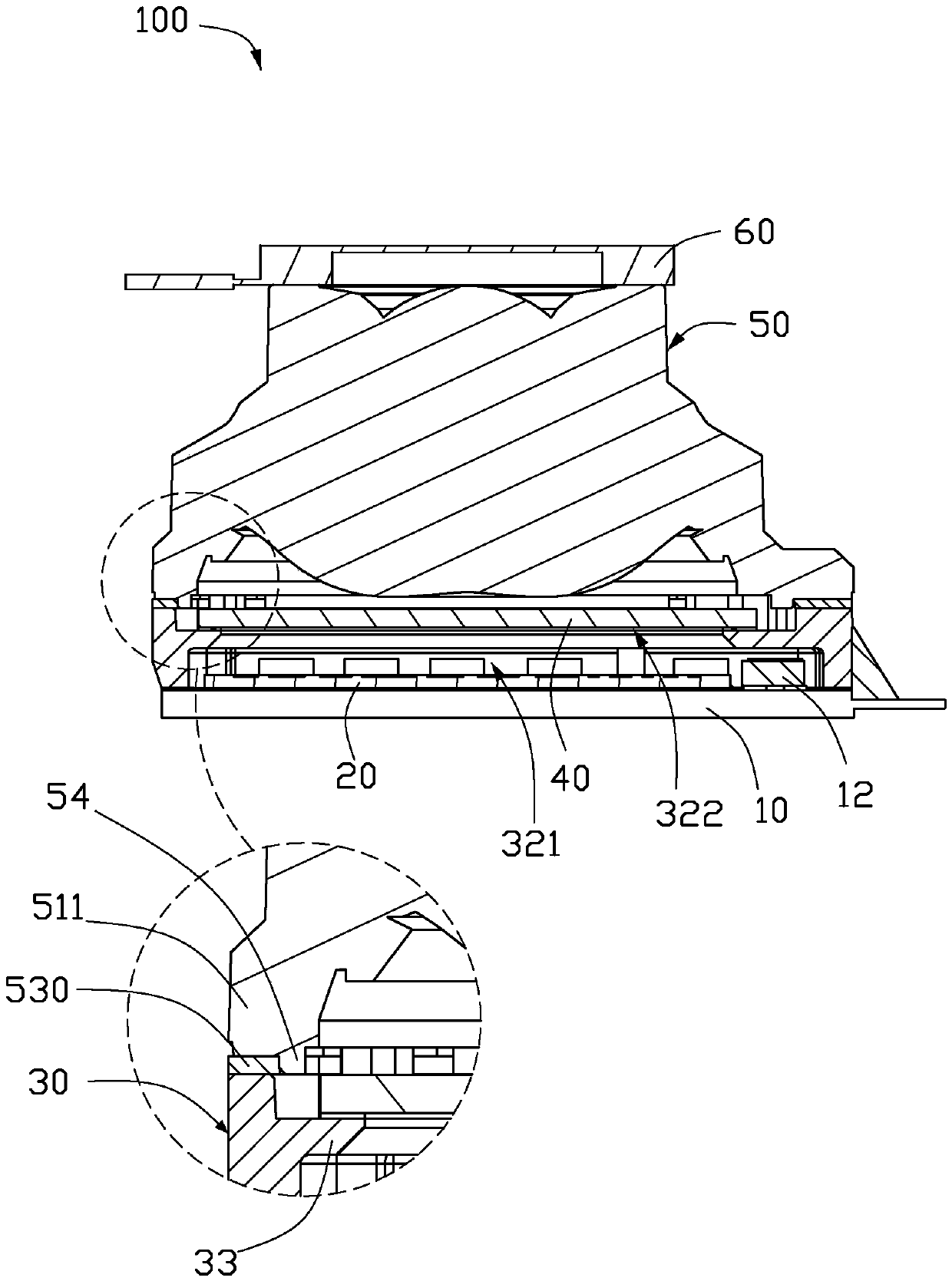
Lens module

A lens module and lens technology, which is applied in the field of photography, can solve problems such as cracking, image delay, and adhesive layer deformation, so as to ensure the shooting quality and prevent delay

Active Publication Date: 2020-01-07
TRIPLE WIN TECHSHENZHEN CO LTD +1
View PDF10 Cites 1 Cited by
  • Summary
  • Abstract
  • Description
  • Claims
  • Application Information

AI Technical Summary

Problems solved by technology

However, when the lens module is subjected to external force, the adhesive layer will be deformed and cracked, which will cause the lens holder to separate from the mounting bracket, thereby reducing the life of the lens module
Furthermore, strong external light will pass through the adhesive layer and reach the photosensitive chip through a series of reflections in the mirror seat, causing obvious errors in the image, thereby affecting the quality of the image.

Method used


Image

  • Lens module
  • Lens module
  • Lens module

Examples


Embodiment Construction

[0013] The following will clearly and completely describe the technical solutions in the embodiments of the present invention with reference to the accompanying drawings in the embodiments of the present invention. Obviously, the described embodiments are only some, not all, embodiments of the present invention. Based on the embodiments of the present invention, all other embodiments obtained by persons of ordinary skill in the art without making creative efforts belong to the protection scope of the present invention.

[0014] It should be noted that when an element is considered to be "connected" to another element, it may be directly connected to the other element or there may be an intervening element at the same time. When an element is referred to as being "disposed on" another element, it can be directly disposed on the other element or intervening elements may also be present.

[0015] Unless otherwise defined, all technical and scientific terms used herein have the sa...


PUM


Abstract

A lens module comprises a circuit board; the photosensitive chip is fixed on one surface of the circuit board; the hollow mounting bracket is fixed on the circuit board and accommodates the photosensitive chip; the optical filter is fixed on the mounting bracket and is opposite to the photosensitive chip; and the lens unit is fixed on the surface, far away from the circuit board, of the mounting bracket through a hollow adhesive layer, a plurality of bosses are arranged on the surface, fixed on the mounting bracket, of the lens unit, the bosses are positioned on the inner side of the adhesivelayer, and the height of the bosses is greater than or equal to that of the adhesive layer.

Description

technical field [0001] The invention relates to the field of imaging, in particular to a lens module. Background technique [0002] A conventional lens module generally includes a lens, a lens base, a mounting bracket, a filter, a photosensitive chip and a circuit board. Generally speaking, the lens is installed in the mirror base, and the mirror base is pasted on the mounting bracket through an adhesive layer. However, when the lens module is subjected to external force, the adhesive layer will be deformed and cracked, which will cause the lens holder to separate from the mounting bracket, thereby reducing the life of the lens module. Furthermore, strong external light will pass through the adhesive layer and reach the photosensitive chip through a series of reflections in the mirror seat, causing obvious error in the image, thereby affecting the quality of the image. Contents of the invention [0003] In view of this, it is necessary to provide a lens module that can s...

Claims


Application Information

Patent Timeline
Patent Type & Authority Applications(China)
IPC IPC(8): H04N5/225G02B7/02
CPCG02B7/025H04N23/50H04N23/55G02B7/022H04N23/54H04N23/57G02B7/04G02B5/20H04N23/68
Inventor 陈信文马晓梅樊珂华张龙飞
Owner TRIPLE WIN TECHSHENZHEN CO LTD
Why Eureka
Try Eureka