
Thermo-acoustic heat engine acoustic field monitoring method monitoring system

A thermoacoustic system and monitoring system technology, applied in the testing of machines/structural components, measuring ultrasonic/sonic/infrasonic waves, measuring devices, etc., can solve the problem of adding measuring points, the influence of the sound field of the measured system, and limiting the pressure and sealing of the system Performance and other issues, to achieve the effect of reducing influence, simple measurement procedure and high precision

Inactive Publication Date: 2008-07-02
TECHNICAL INST OF PHYSICS & CHEMISTRY - CHINESE ACAD OF SCI
View PDF0 Cites 8 Cited by
  • Summary
  • Abstract
  • Description
  • Claims
  • Application Information

AI Technical Summary

Problems solved by technology

[0005] First of all, the laser Doppler velocimeter can only measure the particle flow velocity of the fluid in the tube when the tube wall can transmit light. In order to use this measurement method in the existing thermoacoustic device, it must be structurally modified. The transparent glass tube replaces the original metal tube section. The introduction of the glass tube limits the pressure bearing and sealing performance of the system, which has a serious impact on the sound field of the system under test. Due to the difference between the experimental tube and the actual thermoacoustic system tube, so Availability of test results is significantly affected
[0006] Secondly, this technology is based on the direct measurement of sound pressure and flow velocity at multiple points. The measuring points are several discrete points in space. There is no position for measuring points in the pipe section, and the values ​​of two adjacent points can only be used for interpolation. The accuracy is affected by the number of measuring points
In other words, in order to improve the measurement accuracy, the number of measurement points must be increased, which will inevitably increase the cost of the measurement system and increase the measurement time.
[0007] Furthermore, this technique cannot be used for real-time measurement of the sound field
Due to the use of laser Doppler velocimeters to measure the particle flow velocity of each measuring point sequentially, it is impossible to measure the particle flow velocity of all measuring points at the same time
For thermoacoustic devices that operate stably, this sequential measurement is feasible, but for devices that operate in an unsteady state, in order to measure the instantaneous sound field, it is required to measure the flow velocity of each point particle in the sound field synchronously, and this method is no longer applicable.

Method used


Image

  • Thermo-acoustic heat engine acoustic field monitoring method monitoring system
  • Thermo-acoustic heat engine acoustic field monitoring method monitoring system
  • Thermo-acoustic heat engine acoustic field monitoring method monitoring system

Examples


Embodiment 1

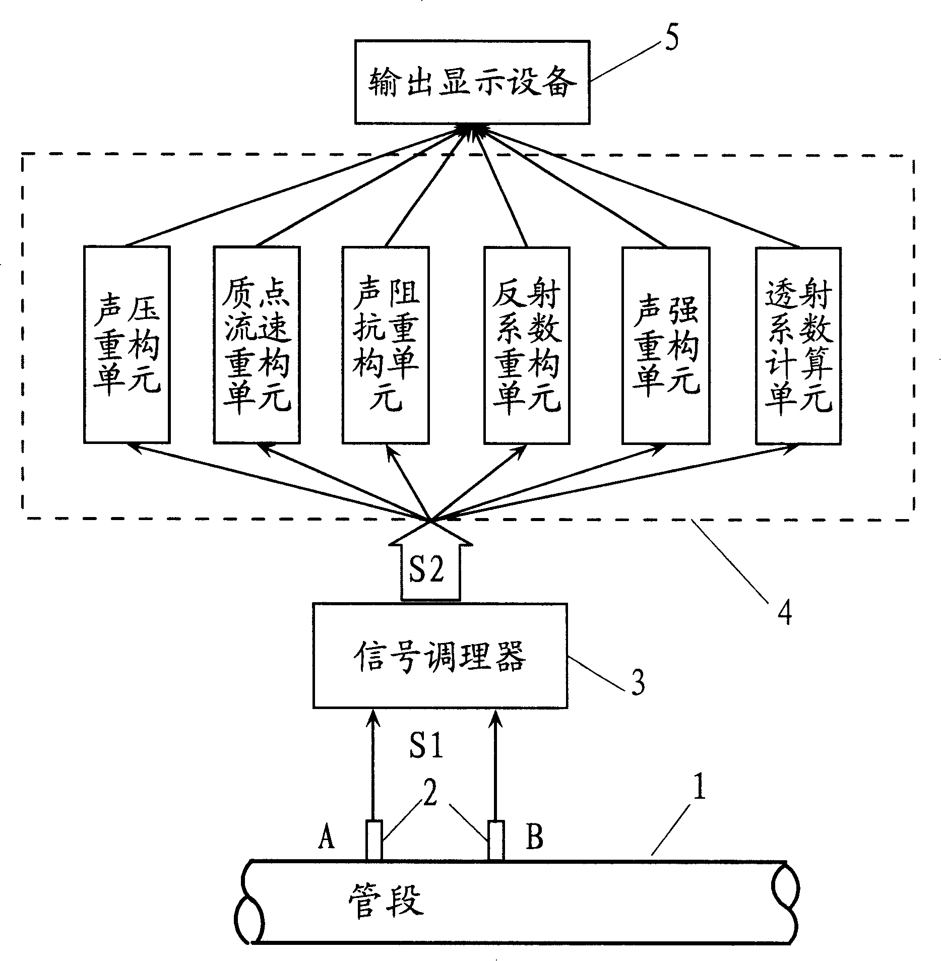
[0049] According to the present invention, refer to figure 1 , two sound pressure sensors 2, respectively denoted by A and B here, are arranged at the sound pressure measuring holes on the pipe wall of the pipe section 1 of the thermoacoustic device. Keep it flat and ensure the sealing of the system from the outside world, so as to minimize the disturbance caused by the measurement system to the sound field.

[0050] The acoustic pressure sensor 2 converts the oscillating pressure of the fluid working medium at its location into a corresponding electrical signal S1. The electrical signal S1 representing the sound pressure from the sound pressure sensor 2 enters the signal conditioner 3 to amplify or reduce the intensity. The conditioned electrical signal S2 representing the sound pressure enters the signal processing device 4 . It should be pointed out that the signal processing device can be composed of a computer with AD conversion function, but various other types of sign...

Embodiment 2

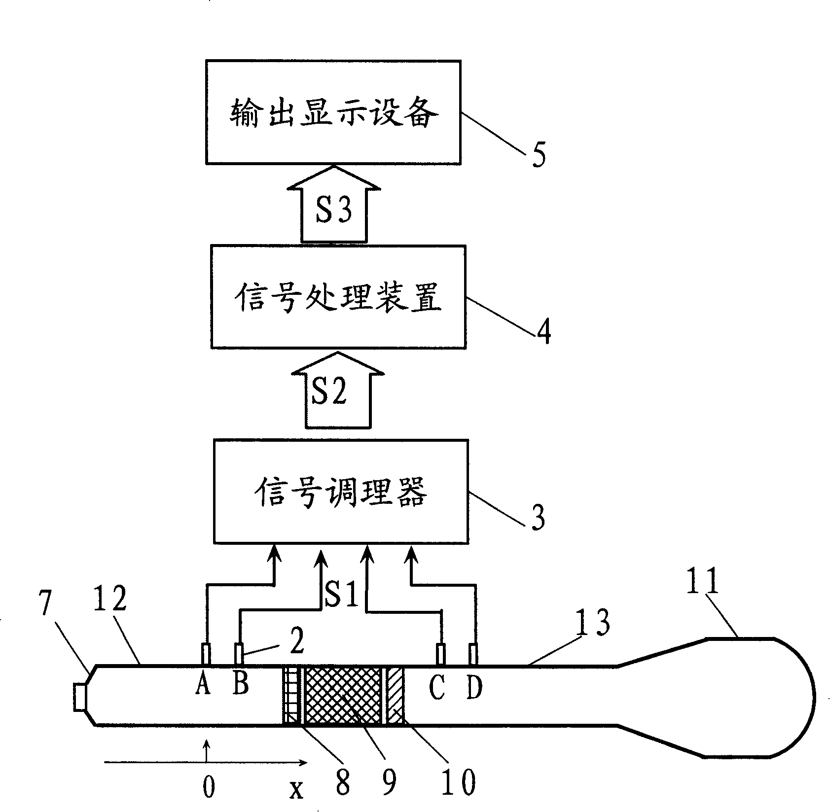
[0080] Figure 8 Another embodiment of the invention is shown, namely its implementation in a standing wave thermoacoustic engine. The standing wave thermoacoustic engine is composed of pipe sections 14 and 15, a hot-end heat exchanger 8 (also called a heater), a regenerator 9, and a cold-end heat exchanger 10 (also called a cooler) and the like. The difference between it and the refrigerating machine in Embodiment 1 is that the refrigerating machine generates cooling effect through the sound work input from the outside (speaker), while the thermoacoustic engine is responsible for generating self-excited oscillation by applying a temperature gradient at both ends of the regenerator , output sound power.

[0081] Although the structure and working principle of the thermoacoustic engine and the refrigerator described in Embodiment 1 are different, the rules followed by the sound field in the resonant cavity of the two are exactly the same, so the sound field reconstruction meth...

Embodiment 3

[0083] Figure 9 Still another embodiment of the invention is shown, namely its implementation in a Stirling-type traveling wave thermoacoustic engine. The Stirling-type traveling-wave thermoacoustic engine has a more complex structure than the standing-wave thermoacoustic engine. Its resonant cavity is composed of two parts: an annular ring and a side branch. A hot-end heat exchanger 8 , a regenerator 9 and a cold-end heat exchanger 10 are arranged in the annular ring, and the resonant tube 18 and the cavity 19 are connected with the annular ring through a joint 20 . The hot end heat exchanger 8, the regenerator 9, the cold end heat exchanger 10 and the joint 20 divide the annular ring into two parts, and the part from the cold end heat exchanger 10 to the joint 20 becomes a feedback pipe, and from the joint 20 to the The part of the heat exchanger on the hot side is called the thermal buffer tube.

[0084] Such as Figure 9 As shown, a pair of pressure measuring holes are...


PUM


Abstract

The invention discloses a sound field monitoring method and a monitoring system for a thermoacoustic engine. The method comprises the follow steps of: (1) measuring the sound pressure of the working fluid in a thermoacoustic system tube with at least two sound pressure sensors; (2) reconstructing the sound pressure distribution of the fluid in the tube with the sound pressure measured by any two sound pressure sensors; (3) reconstructing the local velocity distribution of the fluid in the tube; (4) reconstructing the acoustic impedance distribution inside the tube; (5) reconstructing the reflection factor distribution inside the tube; and (6) reconstructing the sound intensity distribution inside the tube. The monitoring system comprises at least two pressure measuring holes opened on the wall of a measured tube of the thermoacoustic engine, and at least two sound pressure sensors are sealed in the pressure measuring holes corresponding to the pressure measuring holes; the sound pressure sensor is connected with a corresponding signal conditioner, the output signal of the signal conditioner is transmitted to a signal processing device, and the processed result is output and displayed on an output display apparatus. The invention has the advantages of real-time diagnosis and monitoring, and high accuracy.

Description

technical field [0001] The invention relates to thermoacoustic heat engine technology, in particular to a sound field reconstruction method and monitoring system of a thermoacoustic heat engine. Background technique [0002] Thermoacoustic heat engine, including thermoacoustic engine and thermoacoustic refrigerator, is a new type of heat engine with no moving parts and is friendly to the environment. It has received extensive attention since its inception. A thermoacoustic heat engine system usually consists of a thermoacoustic system pipe section, a regenerator, a heat exchanger, and a high-pressure gas working medium. The acoustically driven thermoacoustic refrigerator also includes sound source components. [0003] By setting a sound pressure sensor at a certain point on the pipe wall of the thermoacoustic heat engine, the sound pressure of the oscillating fluid at that point can be measured. In order to further study the law of the sound field inside the thermoacoustic ...

Claims


Application Information

Patent Timeline
Patent Type & Authority Applications(China)
IPC IPC(8): G01H17/00G01H15/00G01M19/00G01M99/00
Inventor 李青牛力李正宇李强
Owner TECHNICAL INST OF PHYSICS & CHEMISTRY - CHINESE ACAD OF SCI
Learn More